Documentation
Renshaw OMP40-2 Optical Machine Probe Manual
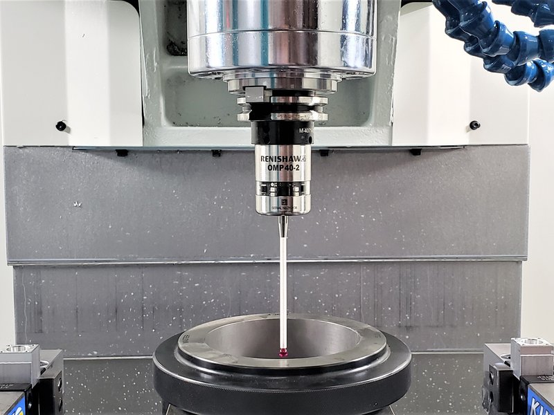
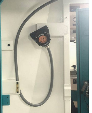
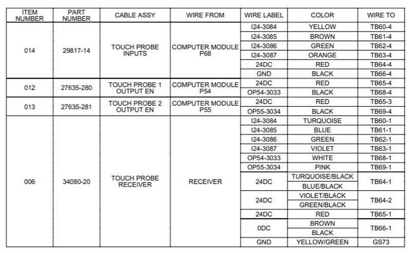
OMI-2T Probe Receiver
The OMP40-2 probe communicates using infrared optical transmission, requiring a direct line of sight (LOS) to the OMI-2T receiver at all times.
 |  |
Service Codes
Code 124 – Probe Part Calibration
- Used to calibrate the part probe.
Code 521 – Hardware Tester
- Used for probe I/O, enable, trigger, and fault verification.
Probe Requirements to Work with ProtoTRAK Software
Before beginning Service Code 124 calibration, confirm that the probe and software are correctly configured.
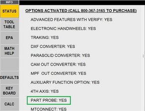
Verify Probe Option Activation
- Run Code 318 and ensure Part Probe Option is active.
- In the STATUS window, confirm PART PROBE = YES under Options Activated.
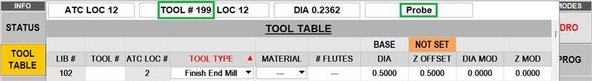
Confirm Library Tool Description
- Ensure the PROBE tool description appears in the top status bar when active.
- Verify the correct LIB #, TOOL TYPE, and OFFSET values display.
- Confirm the Probe tool has a Library # assigned in the Tool Table.
- Delete any ATC tools without a defined LIB # and re-add them as needed.
Internal Probe Settings
Check that OMP40-2 settings match TRAK standards for switch-off method, trigger filter, and transmission power.
Probe Setup Apps

Renishaw offers a mobile app to assist with probe setup:
Apple App Store: Renshaw Probe Set-Up App
Google Play Store: Renshaw Probe Set-Up App
Initialize Battery and Set Power Save
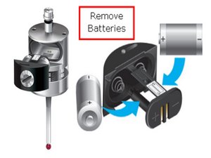
- Use a flat head screwdriver to remove the battery cover from the OMP40-2 probe.
- Take out the batteries, wait 5 seconds, then reinstall them and secure the cover.
- Do not allow coolant or debris to enter the battery compartment.
- Watch for the LED to flash red, then green, then blue.
- When the blue LED appears, deflect and hold the stylus to enter configuration mode.
- Do not remove the batteries while the probe is in configuration mode.
- To exit configuration mode, leave the stylus untouched for 20 seconds.
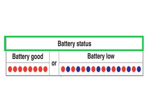
- Battery status will flash: 8 red = good, red + blue = low.
Configure Switch-Off and Trigger Filter Settings
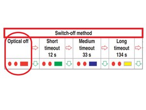
- While still holding the stylus deflected, the switch-off method will be displayed via LED flashes.
- Release the stylus when you see two red flashes followed by a long red flash.
- To cycle through switch-off options, deflect and release the stylus quickly (1 second).
- When the correct setting is shown, deflect and hold the stylus for 4+ seconds to continue.
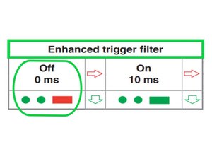
- The trigger filter menu will display as two green flashes followed by a long red flash.
- Deflect and release the stylus to cycle through available trigger filter options.
- When the correct setting appears, deflect and hold the stylus for 4+ seconds.
- The probe will automatically move to the next configuration menu.
Set Transmission and Power Settings
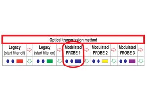
- The optical transmission method menu will display.
- If the probe flashes a color other than blue, deflect and release the stylus (1 second) to cycle through settings.
- Once the probe flashes only blue, deflect and hold the stylus for 4+ seconds to confirm.
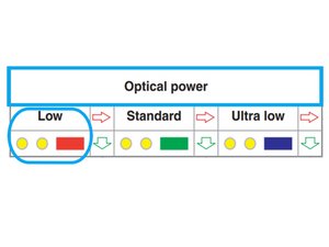
- The optical power setting menu will now appear.
- Deflect and release the stylus until you see two yellow flashes followed by a long red flash.
- Leave the stylus untouched for 20+ seconds to save and exit configuration mode.
Hardware Tester – Probe Detect Check
Use Service Code 521 (Hardware Tester) to verify that the probe and related inputs/outputs are functioning correctly.
In normal operation, the probe will not power on unless the software detects it is loaded in the spindle. This is to preserve probe battery life.
- This behavior does not apply when using the Hardware Tester (Service Code 521), since ProtoTRAK software is not controlling probe power.
Procedure
1. Enter Service Code 521 on the pendant.
- Save and close any open work when prompted.
- Press [Connect]— the “Not Connected” box should disappear.
- Select the correct machine from the dropdown menu.
- There may be up to a 10-second delay before the tester is ready.
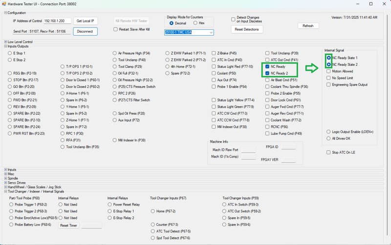
2. Prepare the control for probe testing:
In the right-most Inputs/Outputs column, select:
- [NC Ready]
- [NC Ready 2]
This should cause the NC Ready State 1 and NC Ready State 2 indicators (blue circles) to light.
If they do not light, ensure the [E-STOP] is released, then press and hold the [POWER RESET] button until both indicators are lit.
(Selecting Motion Allowed is optional — only required if you plan to move an axis.)
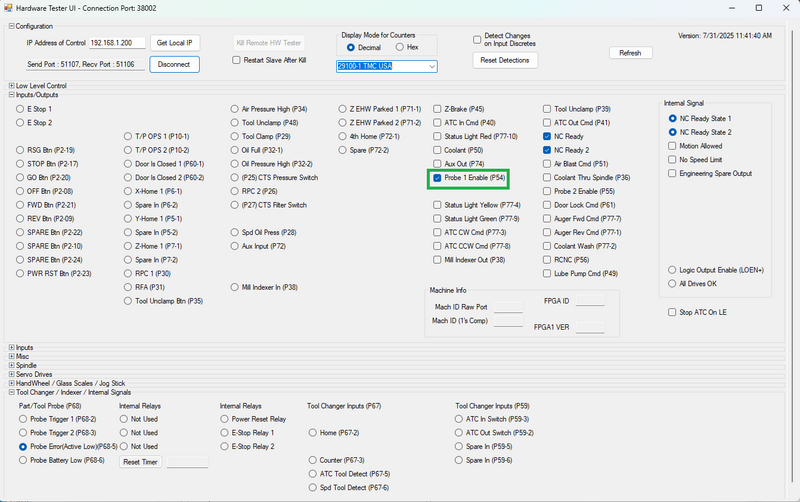
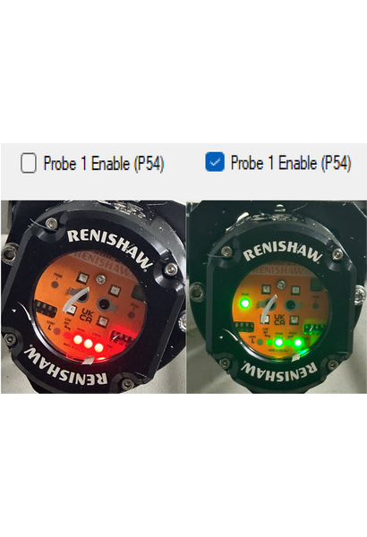
3. Enable the probe:
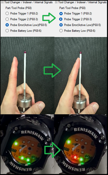
- Select [Probe 1 Enable (P54)].
- Expected behavior:
- Probe Error (Active Low – P68-5) → Enabled (filled circle) = No error.
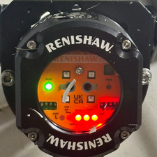
- Probe LED blinks green.
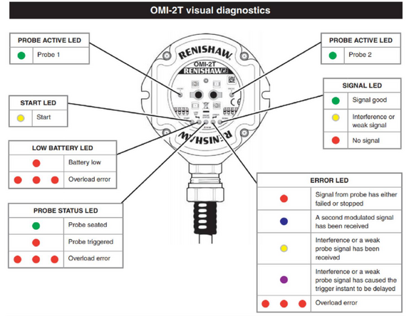
- Receiver LEDs: 1 green LED on the left, 2 green LEDs below (communication OK).
 |  |
4. Trigger the probe:
- While the probe is enabled, deflect the probe stylus by hand.
- Expected behavior:
- Probe Error (P68-5) remains enabled.
- Probe Trigger 1 (P68-2) and Probe Trigger 2 (P68-3) enable (filled circles) while deflected, then return to inactive when released.
To reset the probe deselect [Probe 1 Enable (p54)], wait 5–10 seconds, then reselect it. This reinitializes the probe.
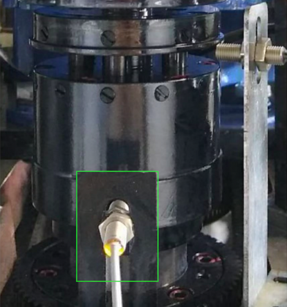
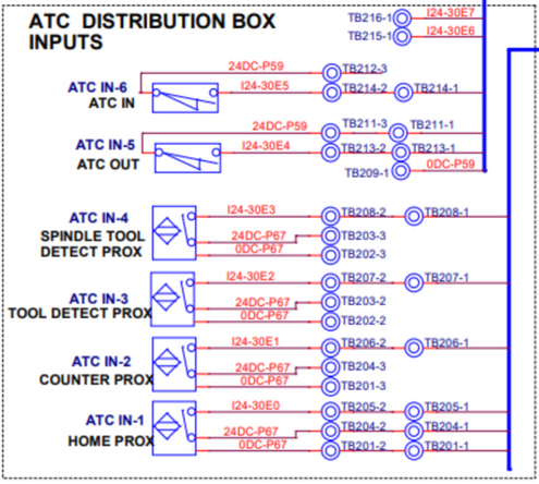
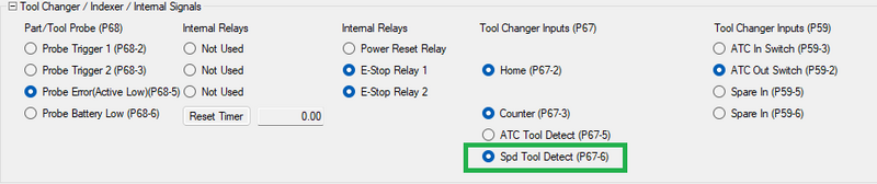
Tool Detect Sensor Check
- Verify that the spindle tool-detect sensor triggers properly when the probe is loaded.
- In normal ProtoTRAK software operation, the probe uses the spindle tool-detect signal as a power-saving feature. The probe will only turn on when the tool-detect sensor confirms the probe is properly loaded in the spindle.
- This restriction does not apply when using the Hardware Tester (Service Code 521), since ProtoTRAK software is not controlling probe power.
 |  |
Loss of Signal / Fault Condition
If [Probe 1 Enable (P54)] is selected and the probe battery is removed or the receiver cannot see the probe:
- Receiver LEDs will show: 1 green LED on the left, 3 red LEDs across the bottom.
- Probe Error (P68-5) will deactivate (empty circle) → fault condition.
- Probe triggers will not respond.
Probe Calibration Procedure
Before You Begin
- Complete XYZ laser calibration and backlash adjustments.
- Confirm Service Codes 123 and 128 have been performed.
Pre-Calibration Requirements
- Set the machine to Metric Mode.
- Ensure the machine is in PRODUCTION OPS mode.
- Ensure the probe tool has a defined Library Number.
- Keep the Feed Rate Override = 100% when running the service code.
- Run the service code with the door closed.
- Always insert the probe in the same orientation relative to the spindle dogs.
- Calibration values depend on the angle at which the probe triggers.
- Measuring in a different orientation than calibration will cause significant inaccuracies.
Setup
1. Install both the probe and optical receiver.
- Have the ring gage and dial indicator ready.
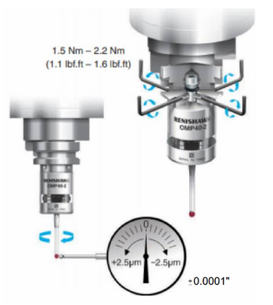
2. Perform Stylus Runout Adjustment.
- Load the OMP40-2 into the spindle.
- Mount a dial indicator to the table and contact the stylus tip.
- Rotate the spindle by hand to check runout.
- Adjust the lower four flat screws in opposing pairs to reduce runout.
- Adjust the upper two pointed screws to fine-tune.
- Repeat lower & upper screw adjustments as needed.
- Target Calibration: ±0.0001".
3. Check probe stability.
- Perform the runout check with a non-probe tool active in the DRO to avoid triggering the probe.
- Use only the first 0.001"–0.002" of indicator travel to avoid stylus deflection.
- After adjustment, switch DRO back to the probe tool.
- While the indicator is still on the tip, push on the lower portion of the probe body (LED section, not the stylus).
- The indicator should deflect and return exactly to zero run-out. Test in multiple directions.
- If it does not consistently return, tighten the tool holder or other set screws until stable.
XY Calibration
4. Place the ring gage in the vise and tighten finger tight (≈10 in-lbs).
5. Use the dial indicator on the spindle to locate exact XY center of the ring gage within 0.0001".
- Set X and Y zero here.
6. Run Service Code 124 for XY calibration.
- Determine the exact ring gage size to 0.001 mm (use marked size, do not measure).
- Nominal stylus diameter = 6.000 mm (0.2362").
7. While running Service Code 124, ensure:
- The machine is in PRODUCTION mode.
- The probe tool is active in the DRO.
- The spindle will orient during the calibration cycle.
Note: Not being in PRODUCTION mode will cause a fault.
8. After calibration, save the values.
- The system checks all 12 measured points (30° intervals).
- Each must be between 0.001 mm and 0.200 mm.
- Failure likely means probe tip run-out or incorrect XY zero.
Z Calibration
9. In DRO, obtain a plastic shim (~0.010").
- Mic the center for accuracy (avoid burrs on edges).
- Lower Z over a flat reference surface (table, vise, or 1-2-3 block).
- Adjust until probe tip is just above the surface by shim thickness.
- If drag is felt, raise slightly.
- Set Z to shim thickness in DRO.
- Adjust in 0.0001" increments.
Note: If no shim is available, use a gage block or 1-2-3 block.
10. Being 0.0001–0.0002" too high is acceptable.
Being too low will cause calibration failure.
- Probe typically triggers at 0.005–0.020 mm in Z.
- Z values must be between 0.005 mm and 0.200 mm.
11. Raise head ≈6 mm (0.25") and run Z calibration with SC 124.
- Monitor Z on DRO — the lowest number seen should be negative.
- If not negative, calibration will fail.
12. Save Z values.
Calibration Verification
13. XY Check:
- In DRO, use CENTER/CIRCLE function multiple times.
- Verify with dial indicator — center should be within:
- ±0.0001" to ±0.0002" depending on accuracy of procedure.
14. Z Check:
- Mount a dial indicator on the spindle base, contacting the reference surface.
- Use the probe to touch the surface.
- Move Z up/down, probing the surface each time.
- Indicator should repeat within 0.0002" (0.005 mm).
Important Notes
- Any error in calibration will be reflected in all future probe measurements.
- If another active probe is nearby and its transceiver can “see” your machine’s transceiver, errors may occur. The software should detect and warn.
0 Comments