

This wiki provides a structured summary of the Automation Ready option for TRAK VMCsi machines. Content is sourced directly from the VMCsi Operating Manual (34105) and VMCsi Service Manual (34104).
For an overview of Automation Ready and Auto Door functions across both VMCsi and TCsi platforms, refer to:
From VMCsi Service Manual (34104)
5.2.6 Automation Ready Inputs/Outputs
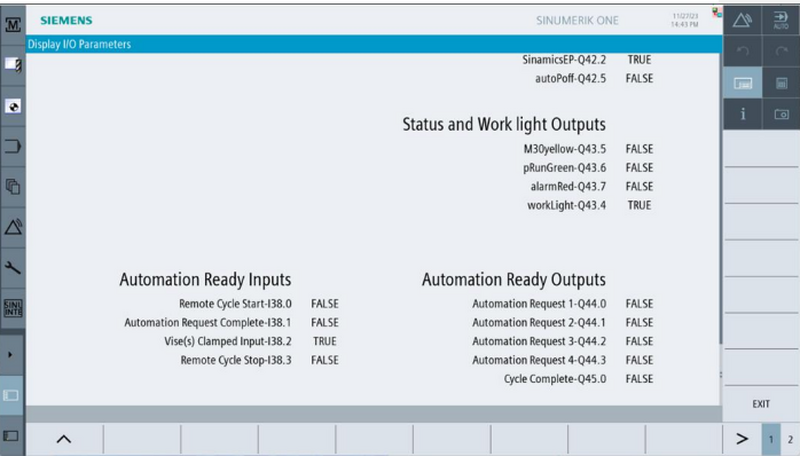
5.3.1 Automation Ready Alarms
| # | Description | Definition |
|---|---|---|
| 700247 | Vise(s) Unclamped | Alarm used to identify when a vise or vises are in an unclamped state. Prevents the machine from running a program. • Can be disabled in TRAK Option screen. • Displays when Vise Clamp input is Low (0V) on I38.2 input. |
| 700959 | Vise(s) Unclamped | Similar to 700247, but allows machine to be manually moved while alarm is active. Can be disabled in TRAK Option screen. |
| 700943 | Waiting for Automation Request 1 to Finish | Triggered by M22; stops axis and spindle until Automation Finish input (I38.1) goes High (24V). • Displays only when “Wait for Finish Input on Automation Request 1” is enabled in TRAK Option screen. |
| 700944 | Waiting for Automation Request 2 to Finish | Triggered by M24; stops axis and spindle until Automation Finish input (I38.1) goes High (24V). • Displays only when “Wait for Finish Input on Automation Request 2” is enabled in TRAK Option screen. |
| 700945 | Waiting for Automation Request 3 to Finish | Triggered by M26; stops axis and spindle until Automation Finish input (I38.1) goes High (24V). • Displays only when “Wait for Finish Input on Automation Request 3” is enabled in TRAK Option screen. |
| 700946 | Waiting for Automation Request 4 to Finish | Triggered by M28; stops axis and spindle until Automation Finish input (I38.1) goes High (24V). • Displays only when “Wait for Finish Input on Automation Request 4” is enabled in TRAK Option screen. |
| 701258 | Automation Request 1 Active | Displays only when “Wait for Finish Input on Automation Request 1” is disabled. • Appears when M22 has been activated along with ON output (Q44.0). • Cleared by M23, E-Stop, or MCP Reset (turns OFF Q44.0). |
| 701259 | Automation Request 2 Active | Displays only when “Wait for Finish Input on Automation Request 2” is disabled. • Appears when M24 has been activated along with ON output (Q44.1). • Cleared by M25, E-Stop, or MCP Reset (turns OFF Q44.1). |
| 701260 | Automation Request 3 Active | Displays only when “Wait for Finish Input on Automation Request 3” is disabled. • Appears when M26 has been activated along with ON output (Q44.2). • Cleared by M27, E-Stop, or MCP Reset (turns OFF Q44.2). |
| 701261 | Automation Request 4 Active | Displays only when “Wait for Finish Input on Automation Request 4” is disabled. • Appears when M28 has been activated along with ON output (Q44.3). • Cleared by M29, E-Stop, or MCP Reset (turns OFF Q44.3). |
From VMCsi Operating Manual (34105)
4.8.1 Automation Ready Feature Descriptions
| Feature | Type | Description |
|---|---|---|
| Remote Cycle Start | In | Starts any program that is loaded and ready, same as pressing Cycle Start on MCP. |
| Remote Cycle Stop | In | Stops the program execution at any point, same as pressing Cycle Stop. |
| Automation Request 1–4 | Out | Controlled by M-codes (M22–M29). Can be set ON/OFF; optionally pauses CNC until Automation Finish input is received. |
| Automation Request Finish | In | Signals that the robot/PLC has completed the Automation Request, allowing CNC cycle to continue. |
| Vise(s) Clamped | In | Detects unclamped state. If unclamped, alarms and prevents program run. Can be disabled in Options. |
| Cycle End | Out | Turns ON when M30 (End of Program) is executed. |
| E-Stop | In | Dual normally-open contacts. Must be closed for CNC to run; opening triggers Emergency Stop. |
| E-Stop | Out | Relay contacts mirror CNC E-Stop state to external automation. |
| Automation Ready On | Out | Indicates Automation Ready is enabled in CNC Options menu. |
| Automation Ready Off | Out | Indicates Automation Ready is disabled. |
| Front Door Close | Out | Relay contacts indicate operator front door is fully closed. |
| Front Door Open | Out | (With Auto Door option) Normally open contact that closes when front door is fully open. |
| Side Door Open | Out | (With Auto Door option) Normally open contact that closes when side door is fully open. |
| Side Door Close | Out | Pair of relay contacts indicating operator side door is closed. |
| Request Front Door Open | In | With Front Door Option: triggers front door to open if no E-stop and spindle is not turning. |
| Request Front Door Close | In | With Front Door Option: triggers front door to close if no E-stop condition. |
| Request Side Door Open | In | With Side Door Option: triggers side door to open if no E-stop and spindle is not turning. |
| Request Side Door Close | In | With Side Door Option: triggers side door to close if no E-stop condition. |
| Network Port | — | Used for programming and debugging by the manufacturer. |
4.8.2 Enable / Disable Automation Ready
TRAK has a customized screen available for enabling and disabling the Automation Ready Options.
To access the screen, at the upper right corner of the display, press [M], press "SETUP" from the left VSK menu bar then press TrakMT Options.

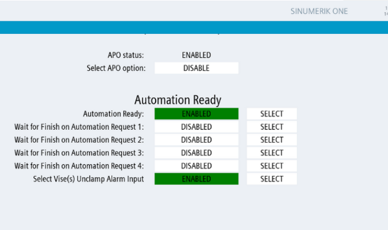
Scroll down to the Automation Ready section.
Automation Ready can be enabled or disabled in the drop-down menu. The machine does not need to be restarted.
When enabled, all features listed on the specification page will be available.
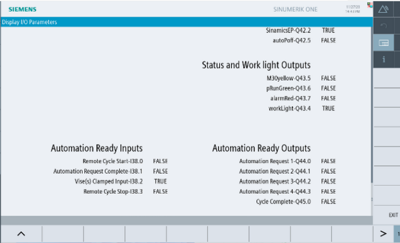
The Wait for Finish Input on Automation Request can be individually enabled.
- When enabled, the CNC waits for the finish signal.
- When disabled, the corresponding M Code will turn the output ON and OFF.
When Select Vise(s) Unclamp Alarm Input is enabled, the machine expects an input from the workholding fixture or vise confirming it is clamped before running.
- When disabled, the CNC ignores the input and runs the program regardless of vise state.
The inputs and outputs can also be monitored in the TRAK Diagnostic Window.
4.8.3 Interface Specifications

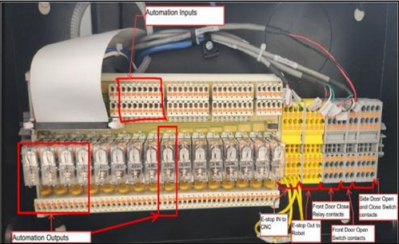
All connections between the CNC and the Automation (Robot) are made in the Automation Ready Box.
All input and output terminals are push-in style.
Recommended wire: 22–16 AWG with ferrule.
4.8.3.1 E-Stop Input to CNC
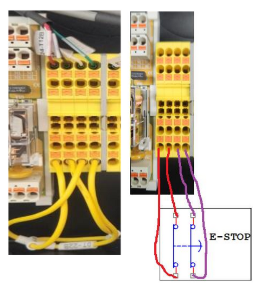
Dual channel E-stop input to CNC. When connecting Automation to the E-stop input terminals, remove jumpers and add contacts to corresponding terminals.
- Channel 1 (24-T12B) between TB901 and TB902
- Channel 2 (0-T22B) between TB903 and TB904
- Internal Circuit Power 24V, 100mA
4.8.3.2 E-Stop Output to Automation (Robot)
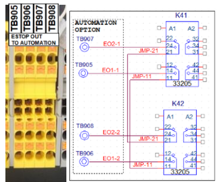
Dual channel E-stop Relay Output contacts. These contacts will open when any of the E-stops is pressed on the CNC or power is turned off.
- Channel 1 (EO1) is between TB905 and TB906
- Channel 2 (EO2) is between TB907 and TB908
- E-stop output circuits are rated up to 250V, 3 amps
4.8.3.3 Front Door Close Output
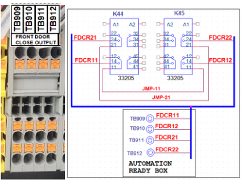
This is a dual channel Relay Output contact. These contacts will open when the Front Door is not fully closed.
- Channel 1 (FDCR11 & FDCR12) is between TB909 and TB910
- Channel 2 (FDCR21 & FDCR22) is between TB911 and TB912
- Door Close circuits are rated up to 250V, 3 amps
4.8.3.4 Automation Ready Outputs
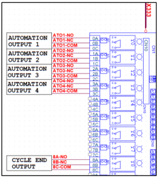
Automation Request and Cycle End:
Circuit and relay contact output SPDT, 250V, 3A.
- Automation Request 1: Relay-Y0, Internal Signal: Q44.0
- Automation Request 2: Relay-Y1, Internal Signal: Q44.1
- Automation Request 3: Relay-Y2, Internal Signal: Q44.2
- Automation Request 4: Relay-Y3, Internal Signal: Q44.3
- Cycle End (M30): Relay-Y8, Internal Signal: Q45.0
4.8.3.5 Automation Ready Inputs
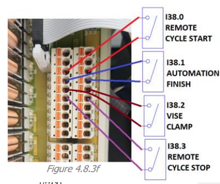
Inputs require a contact closure between P0 and the associated input to activate.
- Input nominal rating: 24V 10mA, Sourcing Digital input
- P0 provides internal 24V for inputs
- (Remote Cycle Start), Signal: I38.0
- Connection: P0 & A2 terminals on x333 I/O board
- (Remote Cycle Stop), Signal: I38.3
- Connection: P0 & B3 terminals on x333 I/O board
- (Automation Finish), Signal: I38.1
- Connection: P0 & B2 terminals on x333 I/O board
- (Vise Clamp), Signal: I38.2
- Connection: P0 & A3 terminals on x333 I/O board
4.8.3.6 Front Door Open Output
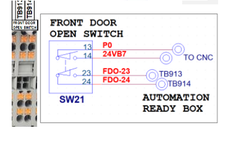
This feature is available with the Auto Front Door Option.
This is a Normally Open single switch contact that is triggered when the Front Door is fully open.
- Circuits Rating Max: 250V, 3 amps
- (FDO23 & FDO24) between TB913 and TB914
4.8.3.7 Request Front Door Open/Close Inputs
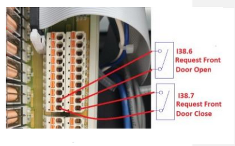
This feature is available with the Auto Front Door Option.
- Input nominal rating: 24V 10mA, Sourcing Digital input
- (Request Front Door Open) Signal: I38.6
- Connection: P0 & A5 terminals on x333 I/O board
- (Request Front Door Close) Signal: I38.7
- Connection: P0 & B5 terminals on x333 I/O board
4.8.3.8 Side Door Open and Close Output
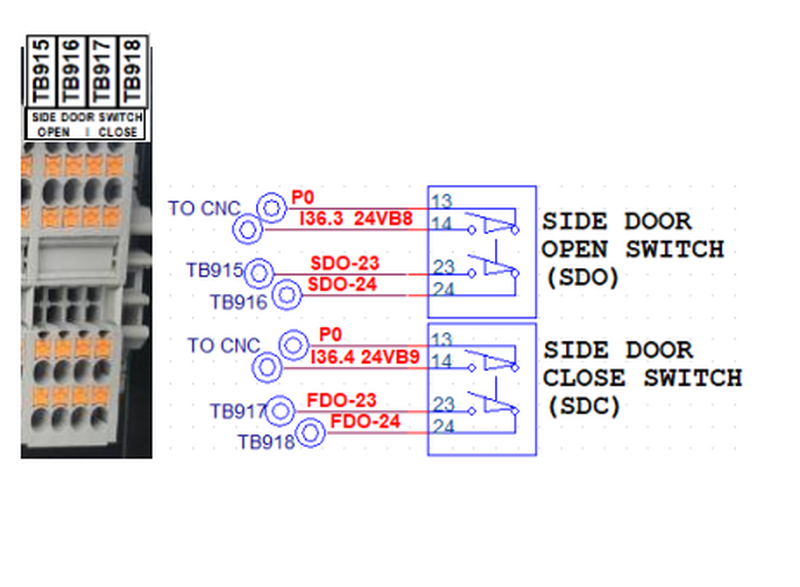
This feature is available with the Auto Side Door Option.
These are Normally Open single switch contacts that are triggered when the Side Door is fully open or fully closed.
- Circuits Rating Max: 250V, 3 amps
- (SDO23 & SDO24) between TB915 and TB916
- (SDC23 & SDC24) between TB917 and TB918
4.8.3.9 Request Side Door Open/Close Inputs
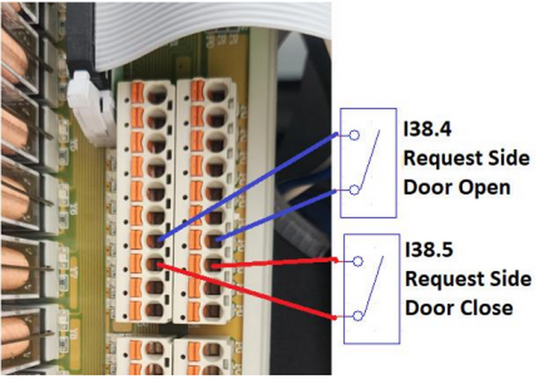
This feature is available with the Auto Side Door Option.
- Input nominal rating: 24V 10mA, Sourcing Digital input
- (Request Side Door Open) Signal: I38.4
- Connection: P0 & A4 terminals on x333 I/O board
- (Request Side Door Close) Signal: I38.5
- Connection: P0 & B4 terminals on x333 I/O board
4.8.3.10 Automation Box Cable Entry Port
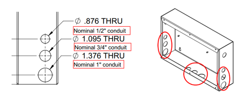
The Automation Box has three sets of 3 different standard hole sizes for attaching conduits or cable glands for wiring all external connections going to a Robot Arm or Automation system.
Each hole is sealed with a panel plug, which must be removed when adding a cable conduit fitting or cable gland.
- Ø .876 THRU – Nominal 1/2" conduit
- Ø 1.095 THRU – Nominal 3/4" conduit
- Ø 1.376 THRU – Nominal 1" conduit
0 Comments