Introduction
In this guide we will cover how to disassemble, clean, and reassemble the Betake and Fonge X chip conveyors for the VMCsi machines.
Tools
No tools specified.
Parts
-
-
Before starting any maintenance on the VMCsi conveyor system you need to know that there have been two different conveyors used. The following step is how to identify which conveyor you have and which steps in this procedure pertain to the conveyor you are working on. Both conveyors are very similar but there are a few differences worth noting.
-
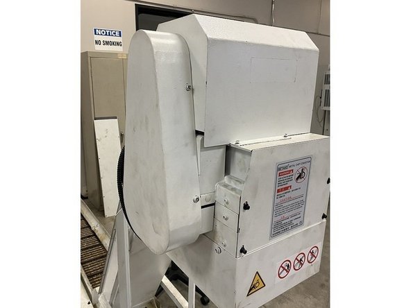
The first and most common conveyor used is the Betake Conveyor. The Betake conveyor has a warning label with the Betake name on it attached to the upper chute access cover. Another way to identify the Betake conveyor is by the chain cover, it is almost perfectly straight up and down.
-
The other conveyor used on the VMCsi machines is the Fonge X. This conveyor is used primarily on the early VMCsi machines. It also has a warning label on the upper chute access cover with the Fonge X name on it. Again this conveyor can be identified by the chain cover, the chain cover on the Fonge X is at an angle instead of vertical.
-
Before starting this procedure vacuum as many of the chips as you can from the topside of the belt. If the conveyor can be moved under power rotate it around so you can remove as many of the chips as possible that may be stuck to the rest of the belt as well.
-
-
-
Steps #2 through #4 are for the Betake Conveyor system. For Fonge X skip to step #5
-
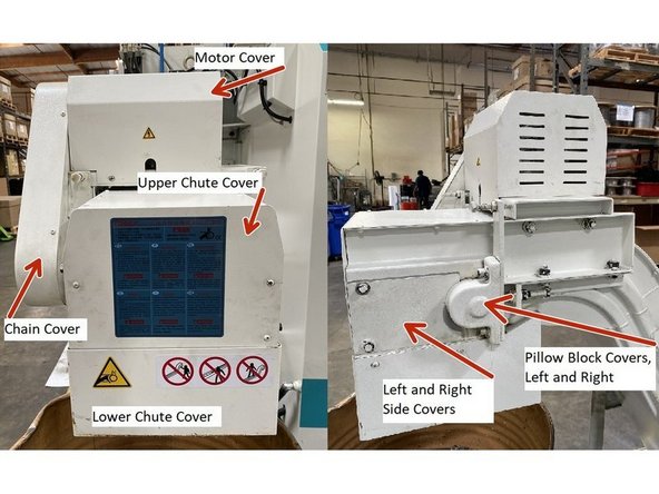
In order to be able to clean the inside of either conveyor you must remove the belt. To gain access to the belt on the Betake Conveyor you must remove the sheet metal covers around the motor and chain. Start by removing the chain cover to expose the chain and drive sprockets.
-
Next remove the motor cover, lower chute cover, and upper chute front cover. Then remove the pillow block cover and both of the small side covers on each side of the conveyor. This will now give access to the motor, chain , sprockets and pillow blocks.
-
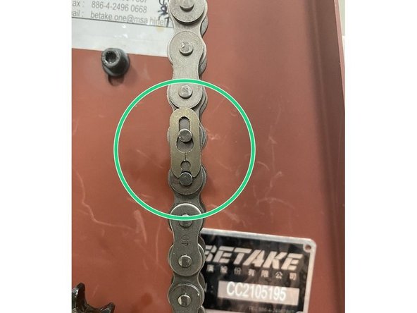
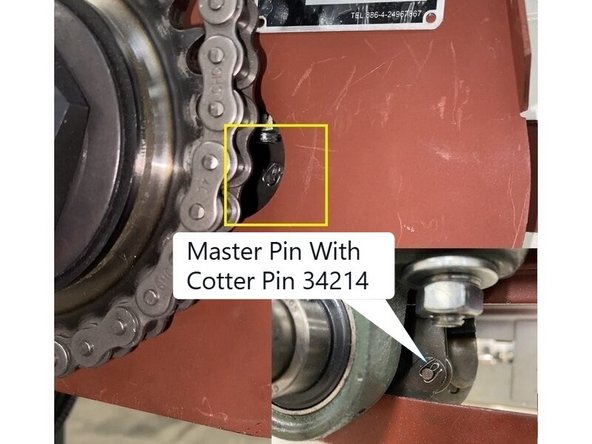
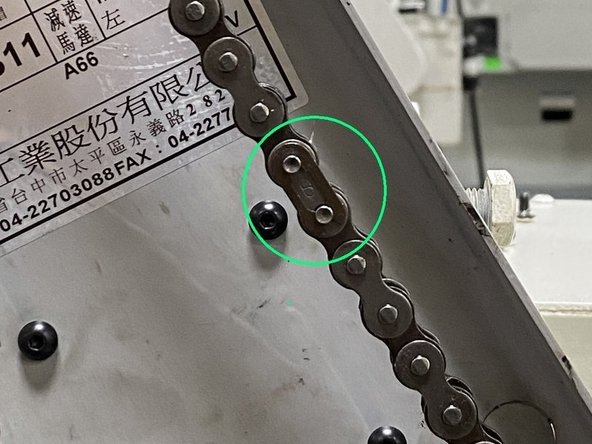
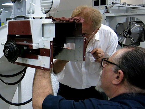
If conveyor can be run under power, jog it around until you can see the master link pin on the belt. It is the pin with the cotter pin in it, and visible from the chain side of the conveyor. Move it to a spot where you can remove the cotter pin and also be able to drive the pin out with a small punch. Do not remove master pin at this time.
-
If you are unable to move the conveyor under power to position the main pin in the belt to where it could be accessed for removal an alternate method is discussed later in the procedure.
-
You can now disconnect the power from the conveyor, and remove the conveyor and coolant tank from the machine so that the conveyor and belt can be removed from the coolant tank and cleaned in an area where there is more room to work around the conveyor.
-
The coolant tank should be drained at this time.
-
-
-
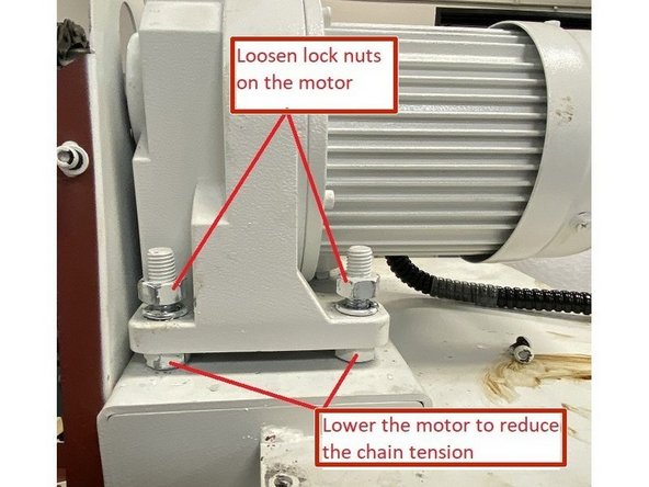
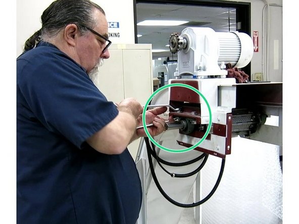
With the motor cover removed, loosen the top nuts on the motor then use the lower nuts to lower the motor down to reduce the tension on the chain.
-
Once the tension has been removed from the chain locate the master link on the chain and remove it then remove the chain from the sprockets.
-
Measure how much of the motor shaft is sticking out of the motor sprocket and record that value so that the sprocket can be reinstalled in about the same place it was removed from.
-
-
-
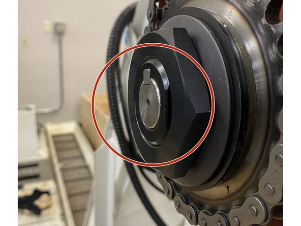
Note that the clutch sprocket is mounted flush with the drive shaft.
-
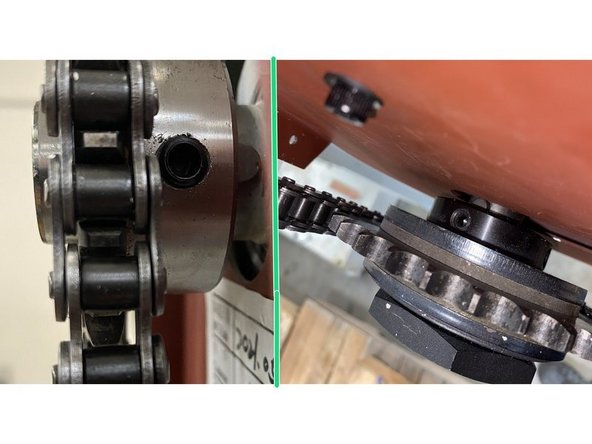
Find the set screws on the motor and clutch sprockets and loosen them. (There are 2 set screws per sprocket.) Remove the sprockets from the motor and drive shaft. Once both sprockets have been removed, remove the woodruff keys from the motor and and driveshaft, then remove the sheet metal cover from behind the sprockets.
-
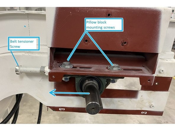
With the sheet metal cover from behind the sprockets removed, you now have access to the pillow block mounting screws and belt tension adjusters. Loosen the pillow blocks and belt tension jam nuts, then loosen the adjusters so that there is no tension being applied to the belt. Push the belt towards the chute to release all tension in the belt.
-
The next 3 steps (#5 through #7) are for the Fonge X conveyor system, skip to step #8 to continue.
-
-
-
To access the belt on the Fonge X Conveyor you need to remove the chain cover, motor cover, upper and lower chute covers, and the left and right side covers.
-
If conveyor can be run under power, jog it around until you can see the master link pin on the belt. It is the pin with the cotter pin in it, and visible from the chain side of the conveyor. Move it to a spot where you can remove the cotter pin and also be able to drive the pin out with a small punch. Do not remove master pin at this time.
-
If you were unable to move the conveyor under power to position the main pin in the belt to where it could be accessed for removal an alternate method is discussed later in the procedure.
-
Photo of master pin with cotter pin is of the Betake conveyor but Fonge X conveyor uses the same type of system. Enlargement in photo 2 shown with cover and sprocket removed for clarity.
-
You can now disconnect the power from the conveyor, and remove the conveyor and coolant tank from the machine so that the conveyor and belt can be removed from the coolant tank and cleaned in an area where there is more room to work around the conveyor.
-
The coolant tank should be drained at this time.
-
-
-
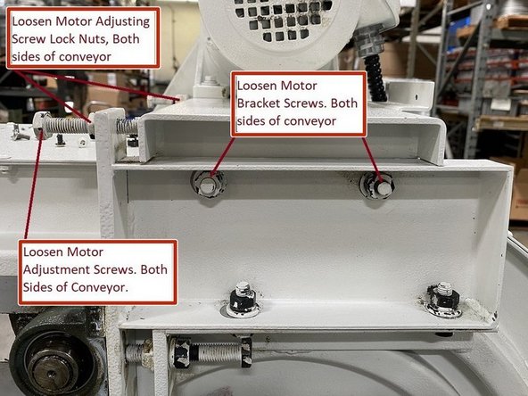
With the covers removed loosen the motor bracket and motor adjustment lock nuts on each side of the conveyor. Loosen the adjustment screws and push the motor towards the adjustment screws to release the tension from the chain.
-
With the tension from the chain removed, locate the master link and remove it, then remove the chain from the sprockets.
-
Measure how much of the motor shaft is sticking out of the motor sprocket and record that value so that the sprocket can be reinstalled in about the same place it was removed from. Also note that the clutch sprocket is flush with the drive shaft so when reinstalling you can install to the same location.
-
-
-
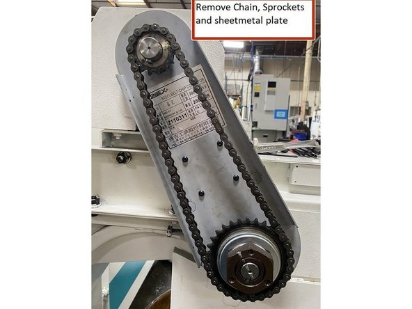
Locate the set screws in the motor and drive sprockets (2 per sprocket) and remove the sprockets and woodruff keys from the motor and drive shafts. Remove the sheet metal panel that was behind the motor and drive sprockets.
-
Remove the pillow block covers and reinstall the pillow block mounting screws and tighten to hold the pillow blocks in place during the belt removal process.
-
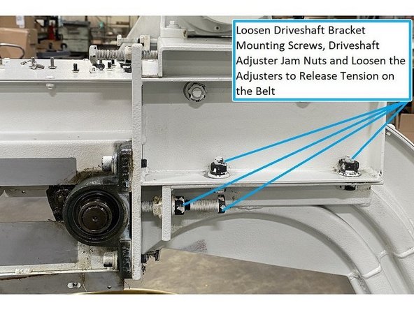
Loosen the four belt driveshaft bracket mounting screws and belt tension adjustment screw lock nuts. Loosen the belt adjustment screws to remove the tension on the belt.
-
-
-
Steps #8 through #12 are the same for both conveyors so only the Betake conveyor is shown in the photos
-
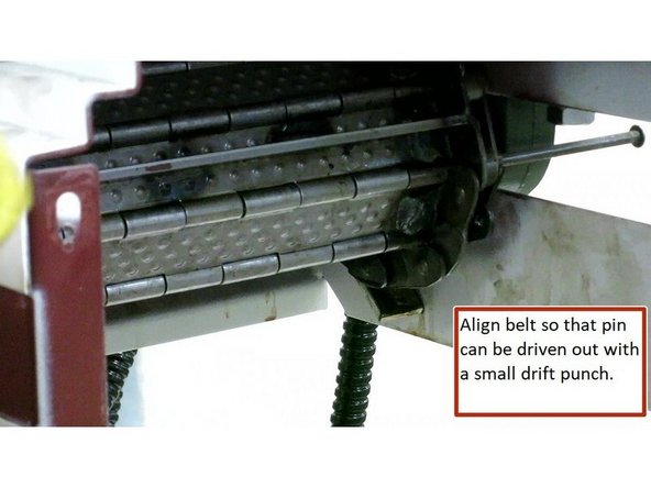
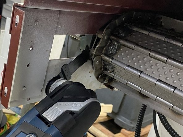
With the sheet metal cover from behind the sprockets removed you should have access to the cotter pin in the belt. Remove the cotter pin and if needed reposition the belt so that the main pin can be removed. (With no tension on the belt you should be able to move it by hand.) Using a small drift punch remove the main pin.
-
You may need to cut or break the cotter pin to be able to remove it.
-
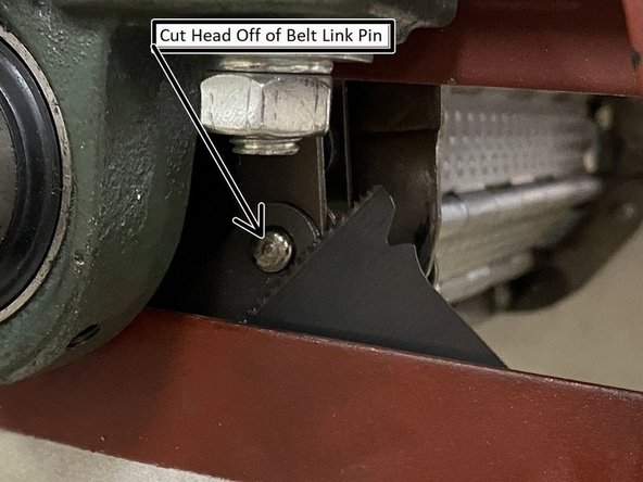
If the conveyor can't be run under power to position the main link pin, it is still possible to remove the belt by cutting the head off of one of the other pins and replacing it with a new link pin and cotter pin. See Photos 2 and 3 for Reference
-
-
-
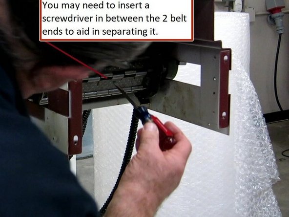
You may need to use a screw driver to assist in separating the belt once the main pin has been removed.
-
It is a good idea to put some pig mat or something similar on the floor to catch the coolant and chips that may come out with the belt.
-
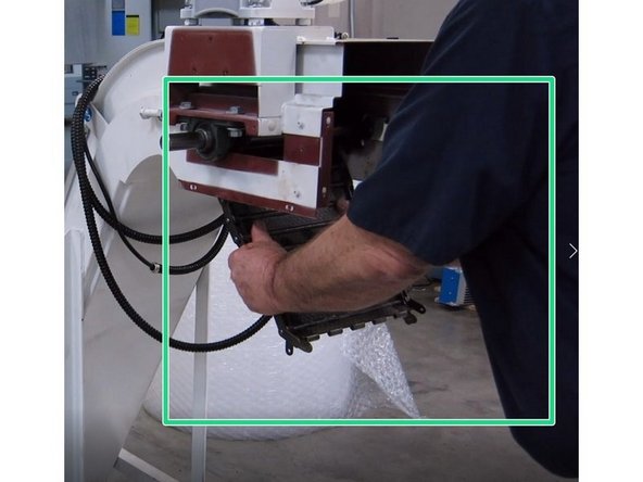
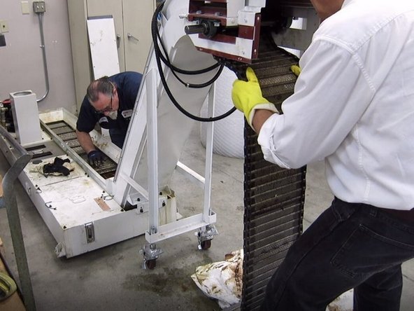
Once the belt has been separated pull the belt down and out of the conveyor folding it as it reaches the floor. With the belt removed, vacuum out the conveyor with a shop vac to remove all of the remaining chips from inside the conveyor.
-
-
-
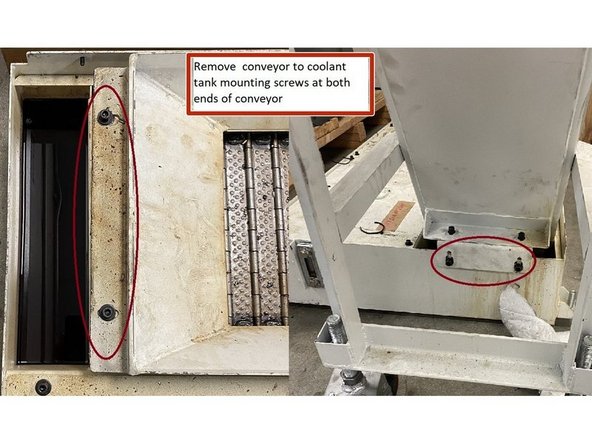
Remove the screws that attach the conveyor to the coolant tank and, using the lifting loops, a strap and some sort of lift, remove the conveyor from the coolant tank. and vacuum out all of the chips in the coolant tank.
-
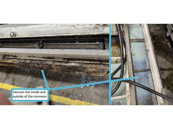
With the conveyor removed from the coolant tank vacuum out the inside and outside of the conveyor to get as many chips as possible out of it. Before reinstalling the belt into the conveyor vacuum the inner side of the belt to remove as many of the chips as possible from it as well.
-
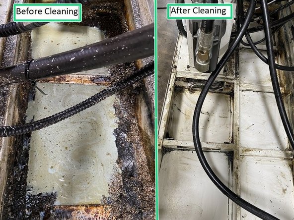
Once the coolant tank has been vacuumed out reinstall the conveyor into the tank.
-
-
-
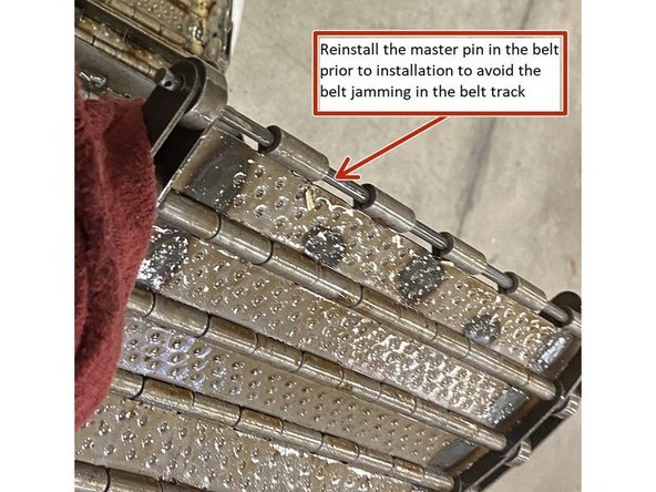
Once the conveyor has been cleaned out, it's time to reinstall the belt. Prior to reinstalling the belt, install the master pin back into the belt making sure to attach it through all of the belt link parts. This will prevent the belt links from jamming up in the belt track and prevent it from being able to be fed all the way through the conveyor.
-
If there are still some chips stuck to the inside of the belt vacuum them out as you are reinstalling the belt if needed.
-
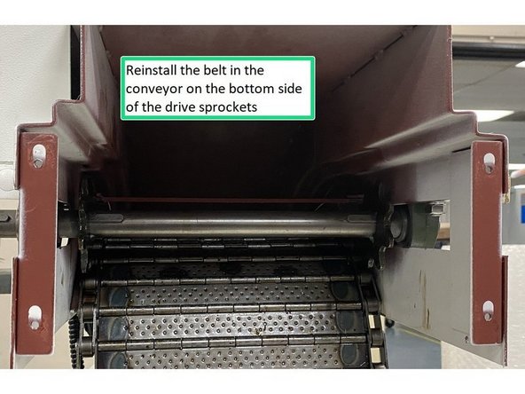
Reinstall the belt in the conveyor on the bottom side of the drive sprockets. Continue pushing the belt into the conveyor until it comes out on the top side of the drive sprocket at the far end of the conveyor. You may need assistance getting the belt around this bend.
-
Once the belt is on the top side of the conveyor you will probably need assistance feeding the belt the rest of the way through the track. One person feeding the belt into the conveyor with the second person at the other end to push it through to the top of conveyor where the main drive sprockets are located.
-
-
-
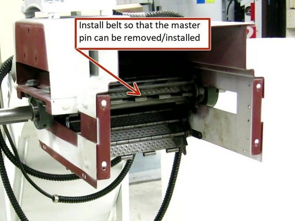
Once the belt has been reinstalled and it is on the top side of the drive sprocket align it so the master pin can be removed. Remove the master pin at this time.
-
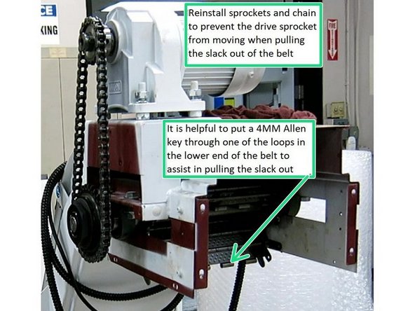
Once the belt has been installed onto the sprocket and aligned so that the master pin can be removed/installed, reinstall the motor sprocket, clutch sprocket and the chain, this will prevent the drive sprocket and driveshaft from rotating when you pull the slack out of the belt and attach it to the bottom side of the drive sprocket.
-
It is helpful to insert an M4 Allen key into one of the master pin loops in the belt to aid in pulling the slack out of the belt and installing it onto the lower half of the drive sprocket. Install the short end of the Allen wrench into the loop and use the long end like a handle to assist in pulling the belt to remove the slack.
-
You could also use a pair of channel locks or something similar to grab hold of the belt to pull with instead of an allen wrench.
-
It may require two people to reconnect the belt, one pulling out the slack and lining up the links and the other installing the master pin.
-
Once the master pin has been started, remove the chain and sprockets so that the belt position can be adjusted if need be, to tap the master pin through the belt. Be sure to align all of the chain link parts with the pin, and once the pin exits the last chain link, install the cotter pin and bend the ends back around the pin.
-
-
-
Once the master pin is in place the belt tension needs to be adjusted.
-
The next three steps (#13, #14 and #15) are how to adjust the belt tension, the chain tension and reassemble the Betake conveyor, for instructions on the Fongex conveyor skip to step #16.
-
To tension the belt tighten the tension adjusting screws by hand until they make contact with the pillow blocks. Using a 19mm wrench evenly tighten the adjustment screws on the drive shaft until you feel the torque to tighten them increase then verify that the conveyor can be rotated by hand then secure the jam nuts.
-
Once the tension has been adjusted and the jam nuts have been secured, tighten the screws in the pillow blocks to hold them in place.
-
-
-
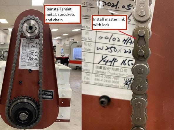
Now that the belt tension has been set and the pillow blocks tightened, reinstall the sheet metal cover that goes behind the motor and clutch sprockets, reinstall the motor and clutch sprockets, woodruff keys, chain and master link with lock.
-
When installing the motor sprocket use the measurement taken earlier to adjust the sprocket on the motor shaft. When reinstalling the clutch sprocket mount it flush to the end of the drive shaft.
-
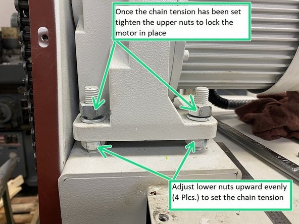
Once the sprockets and chain have been reinstalled adjust the lower motor nuts evenly upward to increase the tension in the chain until the chain has a slight deflection when pressed by hand. Once the chain has been tensioned, tighten the upper motor nuts to lock the motor in place.
-
Verify that when the upper nuts are tightened the chain tension doesn't increase. If it does go back and readjust the motor height so that when the motor nuts are tightened the chain tension doesn't increase.
-
-
-
Reinstall all the remaining sheet metal covers that were removed, reinstall the coolant tank and reconnect to machine. Verify operation and return to production.
-
This concludes the Betake conveyor cleaning procedure.
-
-
-
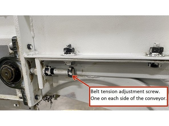
To tension the belt on the Fonge X conveyor, tighten the tension adjusting screws by hand until they make contact with the pillow blocks. Using a 19mm wrench evenly tighten the adjustment screws on the drive shaft until you feel the torque to tighten them increase then verify that the conveyor can be rotated by hand then secure the jam nuts.
-
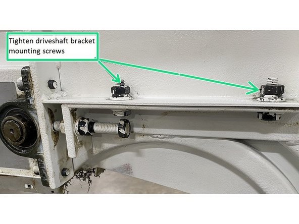
Once the tension has been adjusted and the jam nuts have been secured, tighten the driveshaft bracket mounting screws to secure the driveshaft.
-
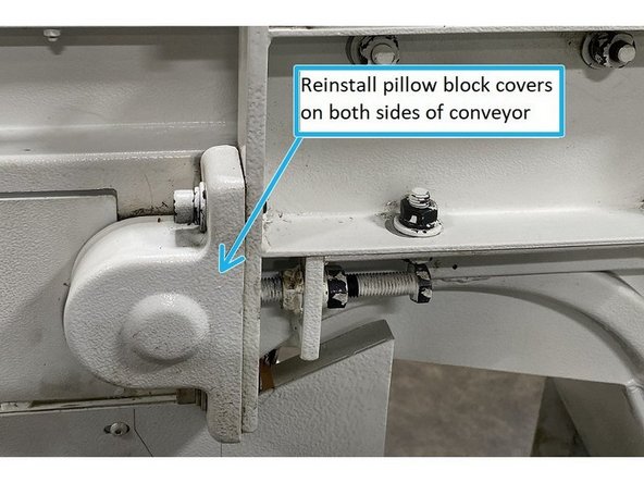
Reinstall the pillow block covers on both sides of the conveyor.
-
-
-
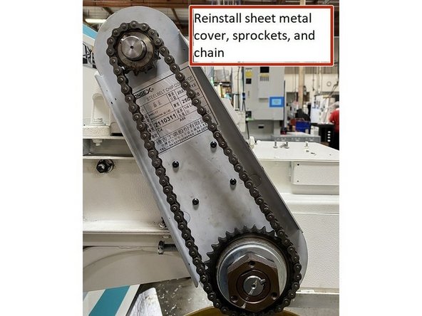
Now that the belt tension has been set reinstall the sheet metal cover that goes behind the motor and drive sprockets. Next reinstall the drive and motor sprockets and woodruff keys to the drive and motor shafts respectively.
-
When installing the motor sprocket use the measurement taken earlier to adjust the sprocket on the motor shaft. When reinstalling the clutch sprocket mount it flush to the end of the drive shaft.
-
Install the chain with master link and lock to the motor and drive sprockets.
-
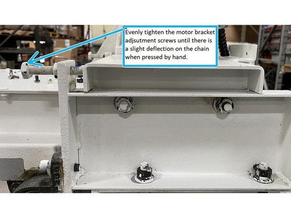
To adjust the chain tension, evenly tighten the adjustment screws until the chain has a slight deflection when pressed by hand. Tighten the jam nuts and then tighten the motor bracket mounting screws
-
-
-
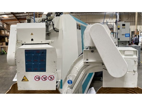
Reinstall all the remaining sheet metal covers that were removed, reinstall the coolant tank and reconnect to machine. Verify operation and return to production.
-
This concludes the Fonge X conveyor cleaning procedure.
-