
Introduction
This procedure provides instructions on the requirements for physically changing the ATC tool pot (34522) on a TRAK VMCsi machining center. The operator must have the knowledge to operate the mill and move the ATC tool changer with the defective pot(s) to the tool change position for pot replacement.
-
-
Orientate the drum until the damaged pot is in the downward position. Do not lower the pot.
-
E-Stop Mill.
-
Before you remove the four screws holding the carousel cover to the carousel, note the orientation of the cover concerning the tool position. There is no physical indicator on the cover to ensure it goes back on the same way, so the numbers point to the correct tool pots.
-
Once you have marked the cover, remove the four 4mm screws holding the carousel cover.
-
Remove the 5mm socket head cap screw of the damaged pot.
-
Push back toward the center of the ATC and then swing down the damaged pot.
-
-
-
Pull the pot forward off the mount and note the orientation of the threaded hole in the pin.
-
Slide the pin out of the pot.
-
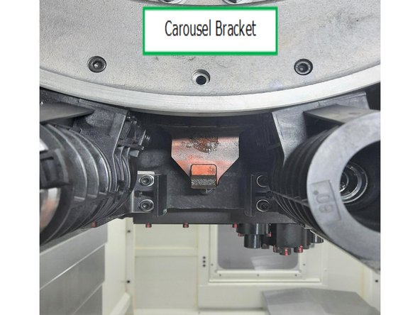
The new pot needs to have the spacer installed, which will rest above the attachment bracket on the carousel chassis. The spacer should be very close to flush with the pot housing.
-
The spacer alignment must have the longer side downward, and the shorter side should match the pot surface.
-
This alignment is crucial. The pot will install and fit on the carousel bracket with the spacer improperly aligned; however, it will not load a tool properly.
-
Check this alignment before proceeding to the next step.
-
-
-
Before replacing the pin, note the orientation of the threads in the center of the pin and align it according to the photo.
-
Reuse the pin removed from the old pot and slide the pin into place on the new pot. Note the orientation of the threaded hole in the pin, as this will make installation easier.
-
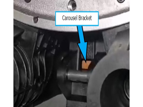
Slide the pot onto the carousel bracket, ensuring that the bracket slides between the pot housing and the spacer.
-
After the pot is positioned on the bracket, you will be able to see the mount through the pot.
-
-
-
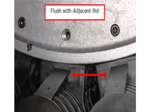
Swing the pot upwards into position and pull it forward until it is flush with neighboring pots and touching the inside of the carousel.
-
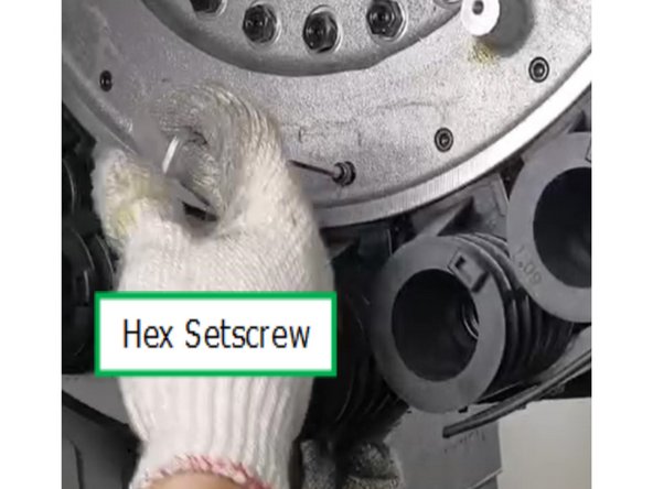
Use a drift or small screwdriver to adjust the threads on the pin inside the hole before replacing the 6mm socket head cap screw. This will make it easier for the threads to catch.
-
A misaligned center pot will show incorrect spacer alignment. After pulling up the pots, verify that the bore is parallel to the neighboring pot. If it is not parallel, the spacer alignment was incorrect.
-
Apply blue Loctite (242) to the 6mm socket head cap screw and tighten.
-
Replace the carousel cover using the correct alignment noted from Step 1.
-
You must test the replacement pot(s) by operating the mill and verifying that all replacement pot(s) can receive their initial tool and exchange the tool for a second one.
-


Cancel: I did not complete this guide.
One other person completed this guide.