
Introduction
This procedure is used to set Z axis height and spindle orientation angle for tool change operation.
If you want to set only spindle orientation angle, you need to go through steps 2, 4, 5, 6 (second and third bullet points only), 11, 12, and 13.
-
-
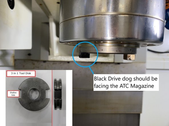
Locate the 3 in 1 Tool Set.
-
-
-
Align markers for the Z-Axis on the rear wall of the mill.
-
Go to [Machine], verify [Act values] is highlighted.
-
MZ1 should read Zero.
-
-
-
Press [DOOR OPEN] button on the MCP.
-
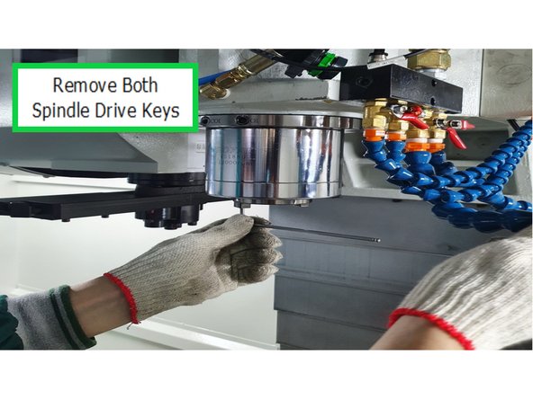
Use hex wrench to remove both spindle drive keys.
-
-
-
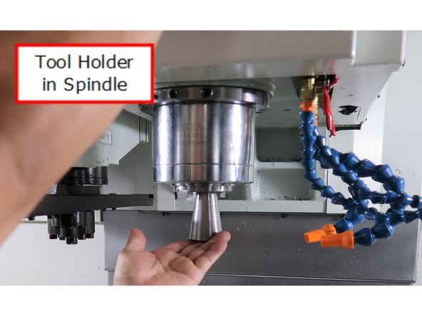
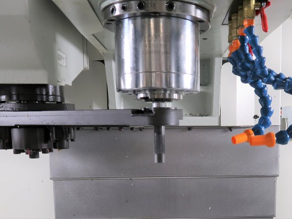
Put 3 in 1 tooling (clamping) tool holder into spindle.
-
Enter Spindle Service Mode:
-
New PLC: Hold down [Spindle Stop] and [Press Feed Stop] rapidly three times to enter into Service Mode. [Feed Start] will be blinking.
-
Old PLC: Hold down [Spindle Stop] and [Press Feed Start] rapidly three times to enter into Service Mode. [Feed Start] will be blinking.
-
Make sure spindle is clear of ATC ARM before rotating the arm.
-
In order to move the ATC arm toward the spindle, press [ARM] and hold [+] button until motion stops.
-
-
-
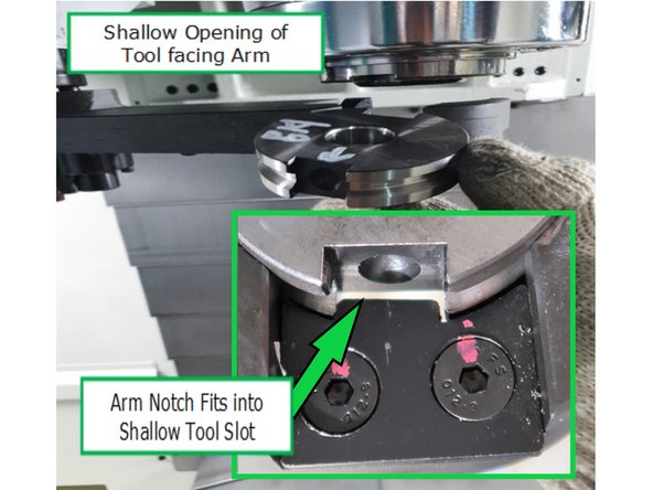
Insert the round disk piece of the 3-in-1 tooling into the ATC arm. Ensure it is oriented correctly—one side is deeper, and the other is shallower.
-
Push the locking lever on the arm while inserting the disk.
-
Refer to the inset photo to align the notch in the arm with the shallow side of the disk. Ensure the notch rests securely in the shallow slot of the round disk.
-
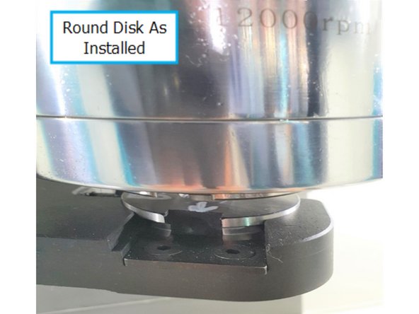
Photo shows close-up view of the shallow side of the disk installed in the ATC arm under the spindle.
-
-
-
Use the alignment bar to make sure the spindle is aligned with the ATC arm on both sides.
-
If it is aligned, proceed to Step 8. If it is not, proceed to Step 7.
-
-
-
Use caution when adjusting heavy machinery.
-
Photo shows adjustment point to move ATC along Y-axis.
-
ATC is pinned along the Y-axis. The pins will need to be removed and re-drilled if you need to move the ATC.
-
Photo shows adjustment point to move ATC along X-axis.
-
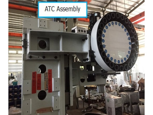
Photo shows ATC during assembly without sheet metal coverings.
-
-
-
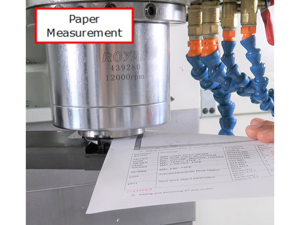
Jog the head down until you can just slide a 0.003-inch sheet of paper between the spindle tool holder and the round disk in the ATC arm, feeling a slight drag on the paper.
-
Record the Z position.
-
Go to [Setup] → [Mach. data]→ [Axis MD] → [Select Axis] → [AX3 Z Axis].
-
Press [Search], enter 30600[0] into the search window. Enter the recorded Z-Axis tool changing position to line 30600(0).
-
Press [RESET PO]
-
-
-
-
Set to Metric: Go to [Machine], verify if measurement is in [inch] or [mm] at the position.
-
If you need to change the measurement to Metric: Go to [Settings] on [Page 2], press [Changeover Metric].
-
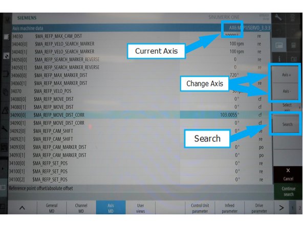
Go to [Setup] → [Mach. data] → [Axis MD] → [Select Axis] → [AX6 Axis].
-
Press [Search], enter 34090[0] and set the parameter value to 0.
-
Press [Reset PO]
-
-
-
Press [JOG] on the MCP, go to [Machine] → [T,S,M]
-
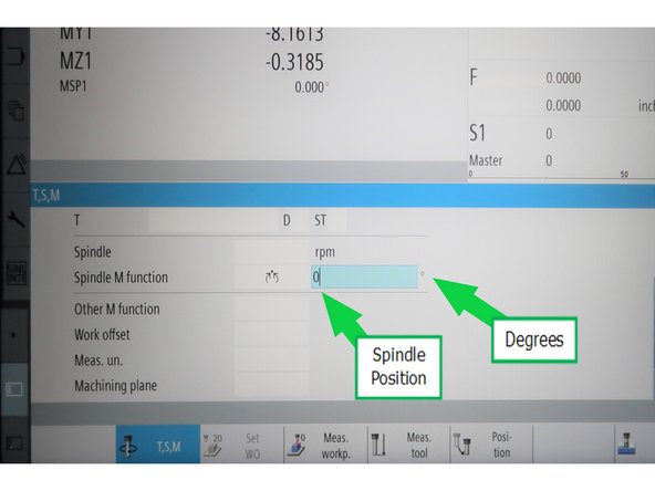
In the [SPINDLE M function] drop-down menu, scroll to the bottom and select [Orient Spindle] using the shown icon.
-
Next to the [Orient Spindle] icon, input 0 as the desired angle.
-
Ensure the door is closed, On the MCP, press [CYCLE START].
-
-
-
Go to [Machine] and press [REF Point] on the MCP.
-
Turn spindle manually to get the angle where the drive key can be inserted (tool changing degree on spindle) – record this position.
-
Press [SPINDLE STOP] before rotating the spindle. Push the spindle dog against the disc keyway in 3 in 1 tool on both the sides, record both values. Take the average of both and record this value.
-
For example, the first value when the dog touches the ARM is 283, second value when the dog touches the opposite side the ARM is 285. To find the midpoint, take the average of the two values: (283 + 285) ÷ 2 = 284.
-
Go to [Setup]→ [Mach. data] → [Axis MD] → [Select Axis] → [AX6 Spindle].
-
Press [Search], enter 34090[0] and set the parameter to the average you calculated. Press [Reset PO]
-
-
-
Remove 3 in 1 tooling
-
Press [ARM] and [-] to bring the arm to the Home position.
-
If [ARM] and [-] does not work, try pressing [ARM] and [+] a few times to return the arm to the Home position. This may require an Unclamp and Re-Clamp of the drawbar.
-
-
-
Press [E-Stop] then power cycle.
-
-
-
Press [CYCLE START]
-
Make sure spindle orientation position is correct in degrees, see Step 4.
-
-
-
Restore spindle drive dogs
-
On machines equipped with a black drive dog install the dog in the spindle facing towards the ATC arm. It is used as a reference of where the shallow side of the CAT40 tool holder should be placed when installing tools into the spindle and magazine.
-
Next step will be to test the tool changer to verify the spindle orientation for this machine is set correctly.
-
-
-
Press [JOG] on the MCP, go to [Machine] → [T,S,M]
-
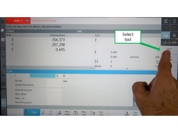
Touch the "T" or Tool selection.
-
Press [Select tool]
-
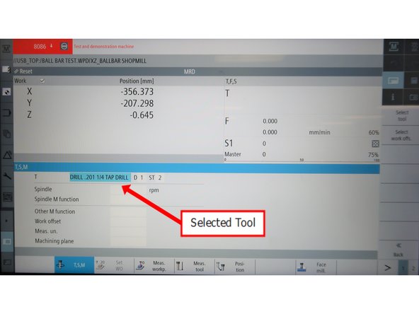
Scroll the Tool Selection and touch the Tool you want to load.
-
-
-
Tool details will appear in the tool field on the screen.
-
Press [CYCLE START] to change the tool.
-
To remove a tool from spindle and return it to the tool holder, select tool "0" and [CYCLE START].
-
This step tests ATC operation. If there is a problem with the tool change, the orientation may be the problem or other failure.
-

![Go to [Machine], verify [Act values] is highlighted.](https://d3t0tbmlie281e.cloudfront.net/igi/trakmtsupport/fAloOIDpYY1APVEE.medium)
![Press [DOOR OPEN] button on the MCP.](https://d3t0tbmlie281e.cloudfront.net/igi/trakmtsupport/LEEwo2vMRKZIsIOA.medium)

![New PLC: Hold down [Spindle Stop] and [Press Feed Stop] rapidly three times to enter into Service Mode. [Feed Start] will be blinking.](https://d3t0tbmlie281e.cloudfront.net/igi/trakmtsupport/1tAQeWynFhCbnEHJ.medium)


![Set to Metric: Go to [Machine], verify if measurement is in [inch] or [mm] at the position.](https://d3t0tbmlie281e.cloudfront.net/igi/trakmtsupport/JhNiJZUFE4cDERAi.medium)
![If you need to change the measurement to Metric: Go to [Settings] on [Page 2], press [Changeover Metric].](https://d3t0tbmlie281e.cloudfront.net/igi/trakmtsupport/tSlsMRnOCsImeJ4J.medium)
![Press [JOG] on the MCP, go to [Machine] → [T,S,M]](https://d3t0tbmlie281e.cloudfront.net/igi/trakmtsupport/VXtLK5CotYsU4J4J.medium)
![In the [SPINDLE M function] drop-down menu, scroll to the bottom and select [Orient Spindle] using the shown icon.](https://d3t0tbmlie281e.cloudfront.net/igi/trakmtsupport/UWhDuibELBmELJWi.medium)
![Go to [Machine] and press [REF Point] on the MCP.](https://d3t0tbmlie281e.cloudfront.net/igi/trakmtsupport/yuMYE26kjtnPfFOV.medium)

![Press [E-Stop] then power cycle.](https://d3t0tbmlie281e.cloudfront.net/igi/trakmtsupport/inUYdsSpU5EX1hWj.medium)
![Press [CYCLE START]](https://d3t0tbmlie281e.cloudfront.net/igi/trakmtsupport/BUfdRjT1jEeH6Rlm.medium)

![Press [JOG] on the MCP, go to [Machine] → [T,S,M]](https://d3t0tbmlie281e.cloudfront.net/igi/trakmtsupport/NA4dFFiOcQBZr2Sg.medium)
![Press [Select tool]](https://d3t0tbmlie281e.cloudfront.net/igi/trakmtsupport/FLbmFGTxZ3sf2Moi.medium)
![Press [CYCLE START] to change the tool.](https://d3t0tbmlie281e.cloudfront.net/igi/trakmtsupport/PaKrSGLKRLiHnGLb.medium)
Cancel: I did not complete this guide.
One other person completed this guide.