Introduction
This guide provides step-by-step instructions for replacing the carousel disc on VMCsi machines, including disassembly, replacement, and reassembly. Linked documents at the bottom include:
34030
34030-1
Manual 24T-30T ATC
Tools
Parts
No parts specified.
-
-
Remove the 11 hex socket screws securing the outer sheet metal cover.
-
Carefully lift and remove the cover.
-
-
-
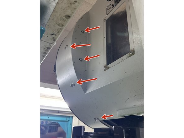
Unscrew the seven hex socket screws securing the gearbox cover.
-
Carefully lift and remove the sheet metal cover with the viewing window.
-
-
-
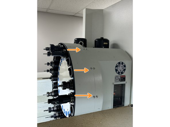
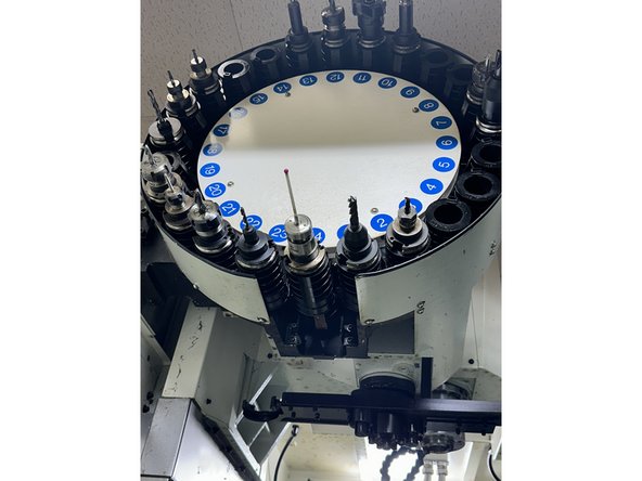
Unscrew the four hex socket screws securing the carousel cover.
-
Remove the cover and set it aside, noting its orientation if the ATC is not marked with position 1 beneath it.
-
-
-
Remove the pods from the bottom of the carousel. Each pod is secured by one screw.
-
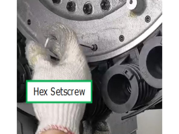
Unscrew the 6mm socket head cap screw on the pot.
-
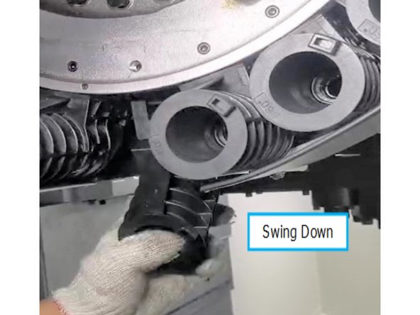
Push the pods back toward the center of the ATC and swing them downward.
-
Pull each pod forward to remove it, noting the orientation of the threaded holes in the pins for reassembly.
-
-
-
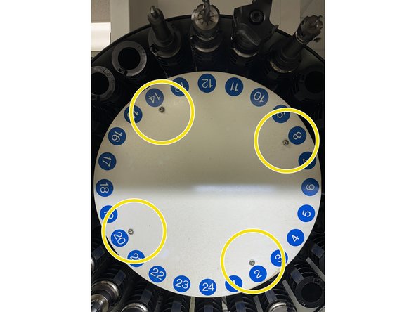
Once all pods are removed, unscrew the center screw on the black metal plate holding the carousel in place.
-
The four outer screws on the center plate are set screws and do not secure the carousel itself.
-
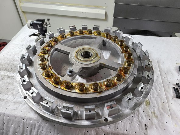
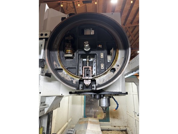
Slide the carousel disc off carefully; it is lightweight but delicate.
-
-
-
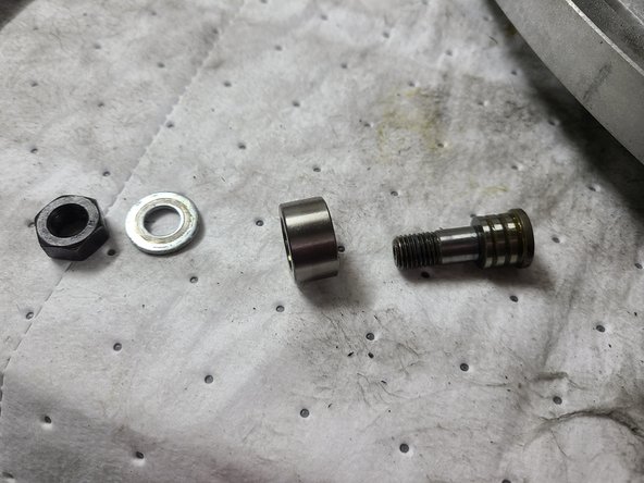
Use a 17mm wrench and 4mm Allen key to loosen and remove the roller bearings, washers, and nuts from the old carousel disc.
-
Inspect bearings for wear and replace if necessary.
-
Install the roller bearings, washers, and nuts onto the new disc, ensuring the correct orientation.
-
Tighten the nuts to approximately 35 lb-ft of torque.
-
Reapply grease to the bearings.
-
-
-
Slide the replacement carousel plate onto the machine, ensuring the segmentation cam and bearings are properly aligned.
-
Secure the carousel plate with the center screw. This screw holds the carousel disc in place.
-
Tighten the four outer set screws to ensure the carousel plate is stable. These screws are used for fine adjustments and should not be over-tightened
-
Verify that the proximity sensor detecting the carousel position is correctly positioned to trigger properly. Look at next step for more details.
-
-
-
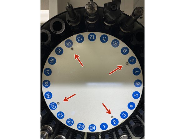
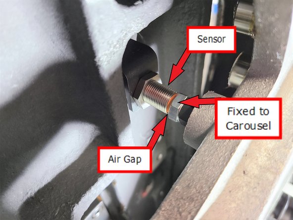
The Home Position Sensor is mounted at a fixed position on the base and triggers when aligned with the steel target on the back of the carousel.
-
Illustration shows a close up of the Home Position Sensor at the home position on the carousel.
-
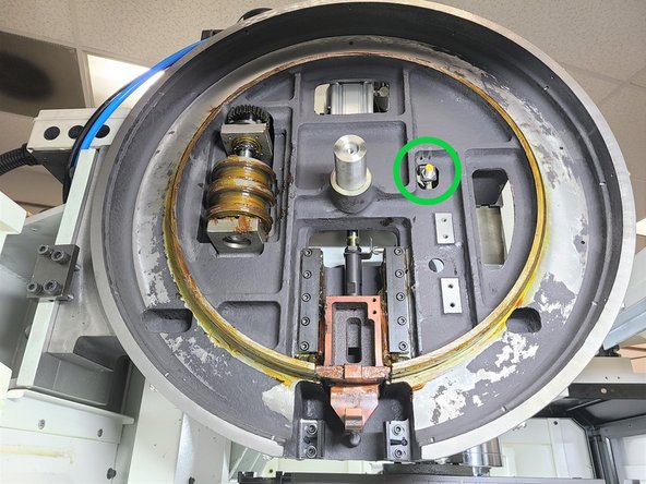
Photo shows switch location with the carousel removed. The Home Position Sensor Is mounted on the base at about the 2:00 position.
-
Air gap should be .080 - .090" or 2 - 2.25 mm.
-
-
-
Slide each pod onto its bracket, ensuring the spacer and bracket align correctly.
-
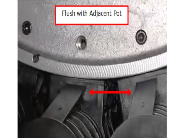
Swing the pods upward and pull them forward until they are flush with neighboring pods and touching the carousel interior.
-
Adjust the threads on the pins using a small screwdriver if needed for easier reinstallation.
-
Secure each pod with its 6mm socket head cap screw and apply a small amount of blue Loctite (242) to the threads.
-
-
-
Replace the carousel cover, ensuring it matches the original orientation.
-
Reinstall the gearbox cover and secure it with its seven hex socket screws.
-
Reinstall the ATC outer cover and secure it with the 11 hex socket screws.
-
-
-
Rehome the ATC system.
-
Perform manual tests of carousel rotation and tool changes to verify smooth operation.
-
Conduct a full CNC-controlled tool change sequence to ensure the system is functioning correctly.
-