Introduction
TRAK includes a Diagnostic I/O custom screen that monitors a wide range of data that is easily accessible on the pendant.
The screen is filled with flags that display “TRUE” or “FALSE”.
- “TRUE” means that the status of an I/O is "1," which means that the particular I/O function has a voltage charge.
- "FALSE" means that the status of an I/O is "0," which means that the particular I/O function has no voltage charge.
The TRUE and FALSE values of an I/O designate a specific behavior for a function on the machine, and if these behaviors do not act in accordance to their assigned values, it means that there is an issue with the machine that needs to be addressed.
-
-
To access the list of Input and Output parameters for your TRAK machine, (1) press the Diagnostics Mode shortcut key on the left-hand side of the screen, and then (2) press the Horizontal Soft Key (HSK) "TrakMT Diagnostics."
-
The "Display I/O Signals" window appears. It lists various inputs and outputs.
-
ATC I/O, Washdown Pump I/Os, CTS Pump I/O, Spindle Cooler I/Os, Coolant Pump I/Os, Chip Conveyor I/Os, Skimmer I/O, Lube Pump I/Os, Guard I/Os, Hand Held Unit (HHU) or EHW I/Os, Control and Status I/Os, Status and Work Light outputs.
-
-
-
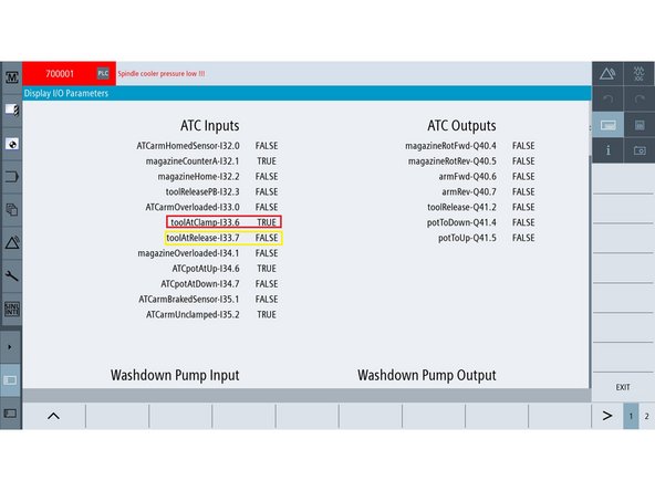
The Diagnostic I/O Custom Screen includes a listing of Automatic Tool Changer (ATC) inputs and outputs as shown in the image.
-
-
-
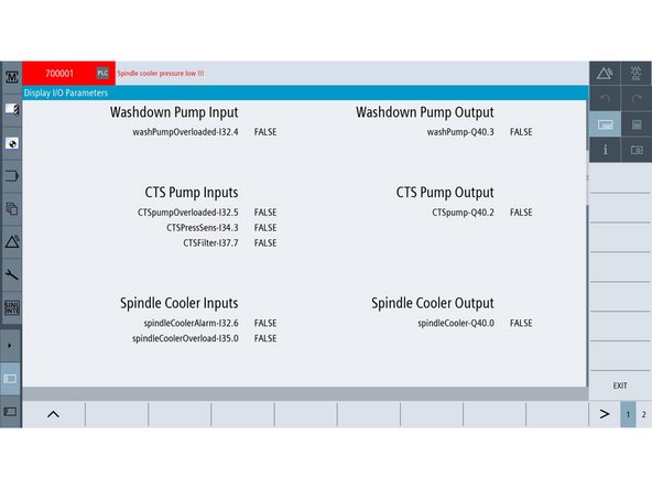
The custom screen also provides a listing of washdown, CTS Pump and Spindle Cooler I/Os.
-
-
-
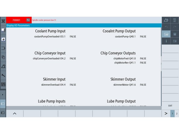
The image on the left shows Coolant Pump, Chip Conveyor, and Skimmer I/Os
-
-
-
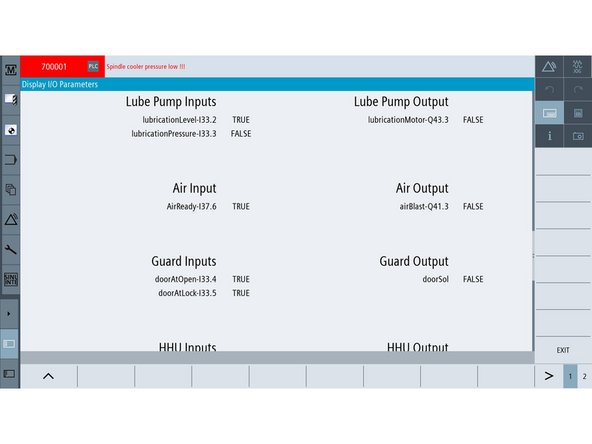
The screen on the left shows Lube Pump, Air, Guard I/Os
-
-
-
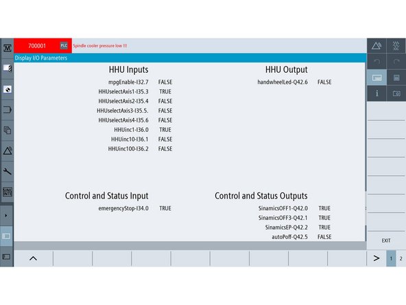
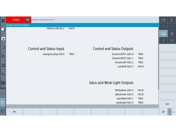
The screen on the left shows Handheld Unit, Control and Status I/Os
-
-
-
The screen on the left shows Status and Work Light outputs
-
-
-
Below are two (2) I/O examples with an explanation of their TRUE and FALSE values:
-
toolAtClamp is an ATC input that is connected to the Tool Clamp/Unclamp function in the spindle.
-
TRUE means the tool in the spindle is clamped. FALSE means the tool in the spindle is released.
-
Alternatively, toolAtRelease is the opposite ATC input of toolAtClamp.
-
TRUE means the tool in the spindle is released. FALSE means the tool in the spindle is clamped.
-
If the machine's behavior is not in accordance with TRUE or FALSE values of a specific I/O, then there is an issue with the machine that needs to be addressed.
-
-
-
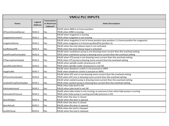
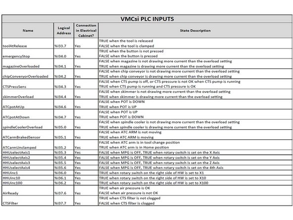
All the input logic is explained in the tables on the left.
-
-
-
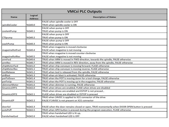
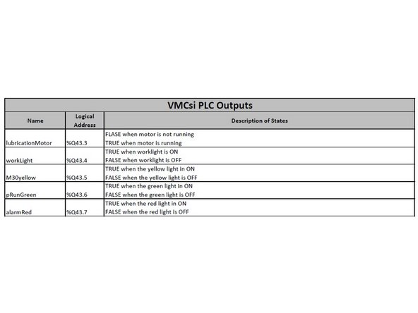
All the output logic is explained in the tables on the left.
-


