Introduction
Trak Machine Tools has two methods of measuring and adjusting the spindle bump out on the VMC2, M10 and M11 machines. With this procedure the user will learn how to correctly adjust the spindle bump out on those machines using both methods.
Tools
Parts
No parts specified.
-
-
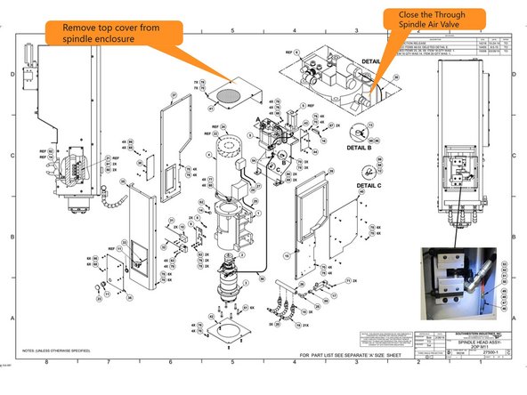
Before you can measure if the spindle bump out needs to be adjusted you first must turn off the through spindle air. The through spindle air can feel like the tool is being bumped out without the drawbar actually making contact with the retention knob on the tool holder to bump the tool out.
-
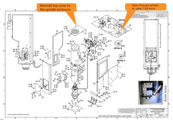
To turn off the through spindle air remove the top cover and close the through spindle air valve.
-
-
-
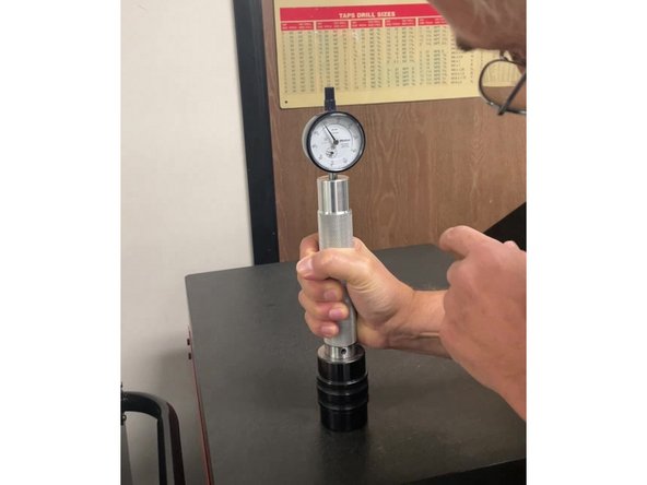
The first method of measuring the spindle bump out is with the Spindle Bump Out Gauge and Calibration Tool. This is the method used in the factory when the machines are being built.
-
First put the spindle bump out gauge into the calibration tool and verify the gauge reads Zero.
-
Next push and hold the spindle clamp/unclamp button on the machine and install the bump out measurement gauge into the spindle and push it up into the spindle. Read the indicator, it should read between 0.020" and 0.030". If the bump out is outside of this it needs to be adjusted.
-
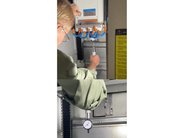
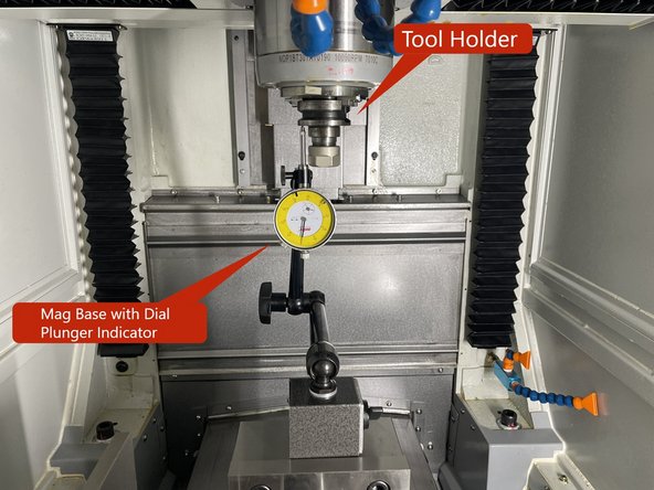
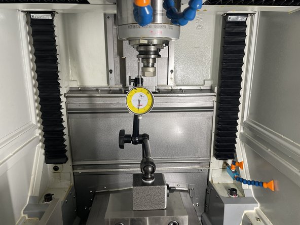
The second method of measuring the spindle bump out is using a mag base and dial plunger indicator. This can be used when the Bump Out Gauge and Calibration Tool aren't available.
-
First put a tool holder in the spindle and clamp it. Using a mag base and a Dial Plunger Indicator, zero it on the shoulder of the tool holder.
-
Next hold the tool holder up into the spindle and press the clamp/unclamp button to unclamp the spindle and read the indicator. The difference from clamped to unclamped should be between 0.020" and 0.030". If it is outside of this range the bump out needs to be adjusted.
-
-
-
To adjust the bump out first remove the Spindle Bump Out Gauge or tool holder from the spindle.
-
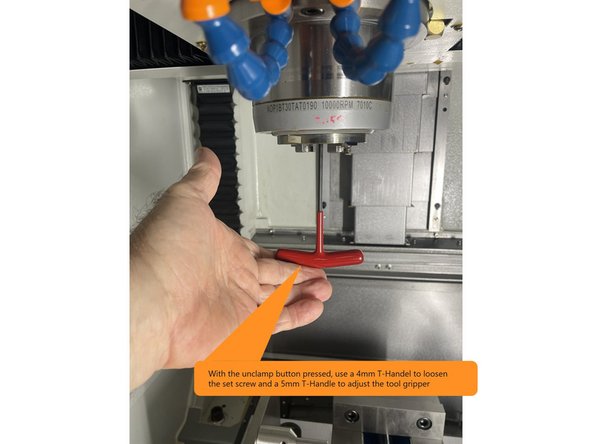
Next unclamp the spindle and with a 4mm T-Handle loosen the set screw in the tool gripper that is inside the spindle.
-
Once the set screw is loose, press the spindle unclamp button again and use a 5mm T-Handle to loosen or tighten the gripper so that there is a 0.020" to 0.030" bump out from spindle clamped to unclamped, then tighten the set screw. Recheck the Bump Out to make sure it didn't change when the set screw was tightened.
-
Note: You will need to reinstall the Spindle Bump Out Gauge or tool holder with mag base and indicator to measure the bump out each time the gripper is adjusted.
-
-
-
Once the Spindle Bump Out has been adjusted turn the through spindle air back on and reinstall the top panel to the spindle cover.
-