Introduction
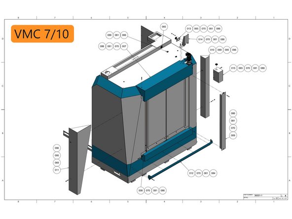
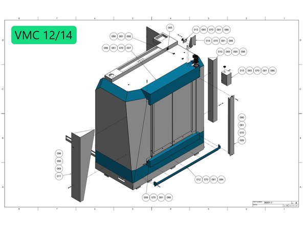
Trak Machine Tools has started offering a series of automation options on our VMCsi series machines, one of them being an Automatic Side Door Option. With this procedure and drawings 36001-1 (VMCsi 7/10), or 36001-3 (VMCsi 12/14) you will be able to install and align the Automatic Side Door Option on the VMCsi series machines. The Programing and testing is covered in the Auto Door Programming Guide
Before starting the "Auto Side Door Option" on the VMCsi 7/10 machines the "Automation Ready Option " (34232-1 VMCsi 7/10) needs to be installed first. For the VMC 12/14 machines the "Electrical Kit -EStop and Door Relay Outputs" (34247-1) needs to be installed first then the "Automation Ready Option" (34232-3 VMCsi 12/14) and then finally the "Auto Side Door Option-VMC 12/14" (36001-3) can be installed.
Tools
Parts
- SWI-TOOL-074 JIG-GROMMET HOLE- SIDE DOOR
- SWI-TOOL-075-1 JIG-COOLANT TRAY- SIDE DOOR × 2
- SWI-TOOL-075-2 JIG-COOLANT TRAY- SIDE DOOR (VMC 7/10) × 2
- SWI-TOOL-075-3 JIG-COOLANT TRAY- SIDE DOOR (VMC 12/14)) × 2
- SWI-TOOL-077-1 FIXTURE-RAIL ALIGNMENT-VMC 7/10 SIDE DOOR
- SWI-TOOL-077-2 FIXTURE-RAIL ALIGNMENT-VMC 12/14 SIDE DOOR
- SWI-TOOL-078-1 JIG-RAIL-DOOR BRACKET-TOP
- SWI-TOOL-078-2 JIG-RAIL-DOOR BRACKET-BOTTOM
- SWI-TOOL-079-1 JIG-RAIL-DOOR BRACKET-UPPER LEFT
- SWI-TOOL-079-2 JIG-RAIL-DOOR BRACKET-UPPER RIGHT
-
-
Before starting the "Auto Side Door Option" on the VMC 7/10 machines the "Automation Ready Option " (34232-1) needs to be installed. On VMC 12/14 machines the "Electrical Kit -EStop and Door Relay Outputs" (34247-1) and the "Automation Ready Options" (34232-3) need to be installed before the "Auto Side Door Option-VMC 12/14" (36001-3).
-
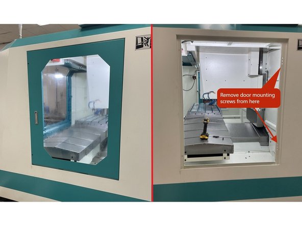
In order to install the Auto Side Door option on the VMC series machines you need to first remove the existing side door.
-
Open the side door and remove the screws that attach the door hinges to the main cabinet and remove the door.
-
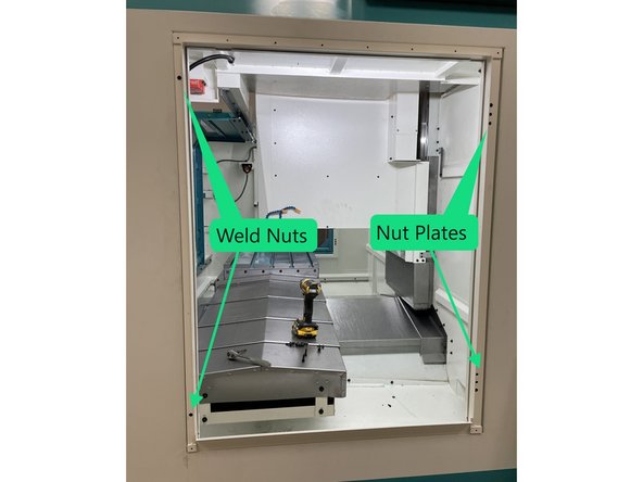
Next install the Door Frame Weldment to the cabinet using 2 nut plates on the right side of the cabinet and 2 weld nuts on the left.
-
-
-
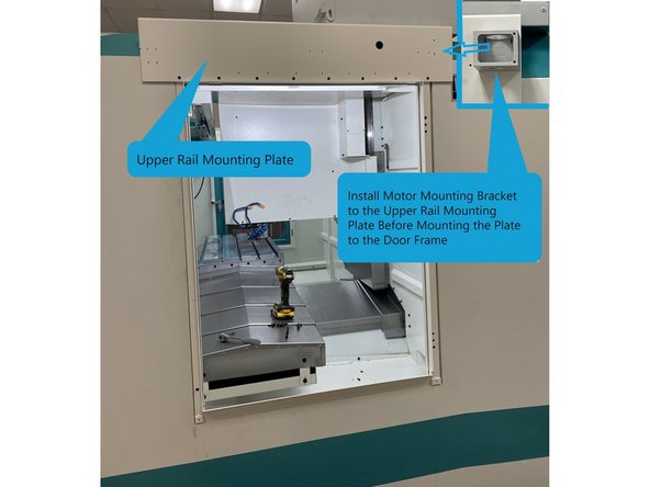
Once the door frame has been installed you need to install the upper rail mounting plate (36104 VMC 7/10 or 36187 VMC 12/14). Note: Install the motor mounting bracket to the upper rail mounting plate before installing the plate to the door frame.
-
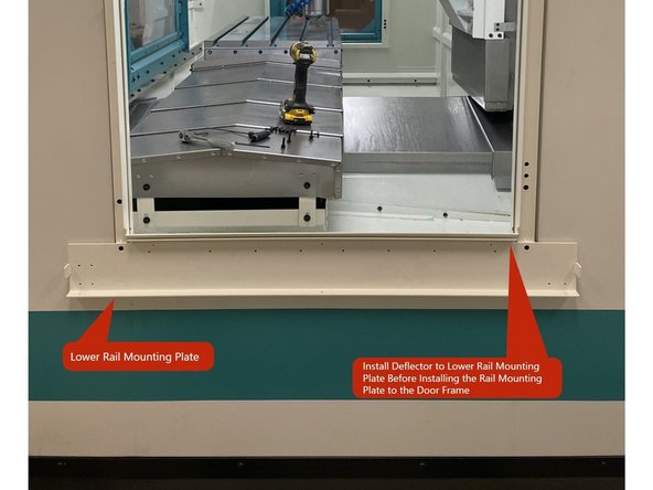
Next you need to install the lower rail mounting plate (36111 VMC 7/10 or 36188 VMC 12/14). First install the deflector (36114 VMC 7/10 or 36204 VMC 12/14) to the lower rail mounting plate then install the lower rail mounting plate to the door frame. See photo 2.
-
-
-
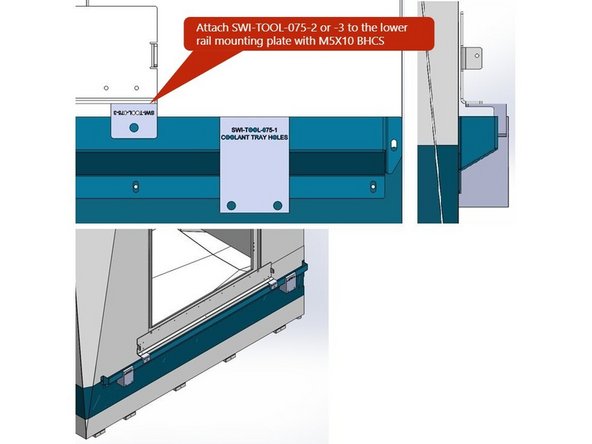
For aid in locating the coolant tray mounting holes we have alignment tools SWI-TOOL-075-2 or -3 (-2 for VMC7/10 and -3 for VMC12/14). Attach them to the lower rail mounting plate with M5X10 BHCS as seen in Image 1.
-
Next place the coolant catch tray up against the jigs on the lower rail plate and place the tool SWI-TOOL-075-1 under the coolant tray on each end to hold it in place against the -2 or -3 jigs as seen in image 1.
-
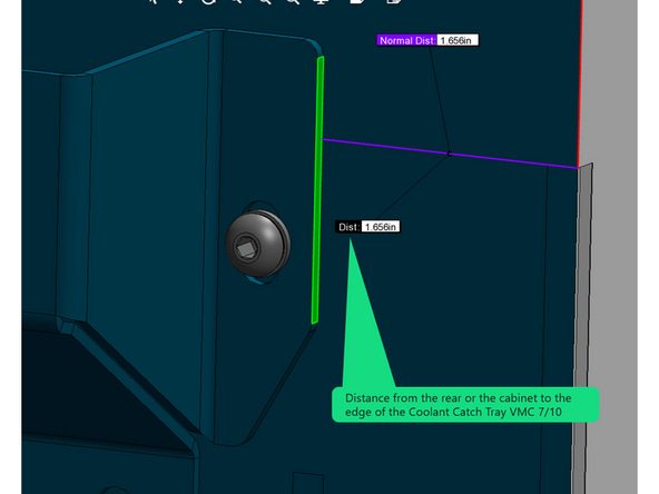
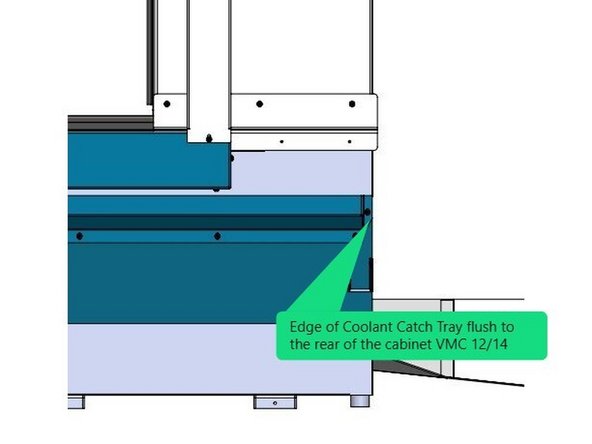
Now align the coolant catch tray so that the edge is 1.656" from the rear of the cabinet for VMC 7/10 machines and flush to the rear of the cabinet for the VMC 12/14. See Image 2 for the 7/10 machines and Image 3 for the 12/14. Verify that the SWI-TOOL-075-1 Jigs didn't move out of position when you adjusted the coolant catch tray into position.
-
-
-
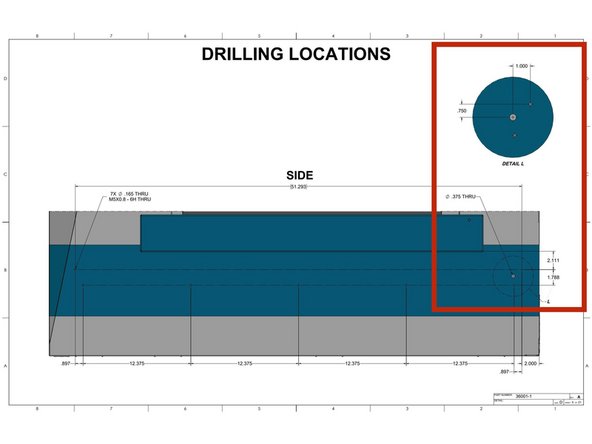
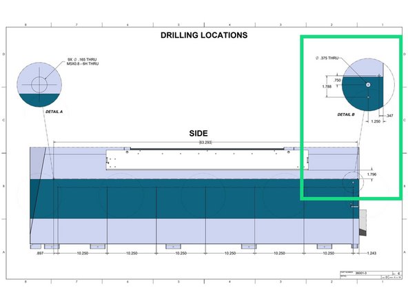
With drawing 36001-1 page 5 locate and drill the Coolant Return hole for the VMCsi 7/10 machines. See Image 1
-
With drawing 36001-3 page 4 locate and drill the coolant return hole for the VMCsi 12/14 machines. See Image 2
-
-
-
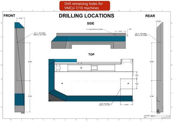
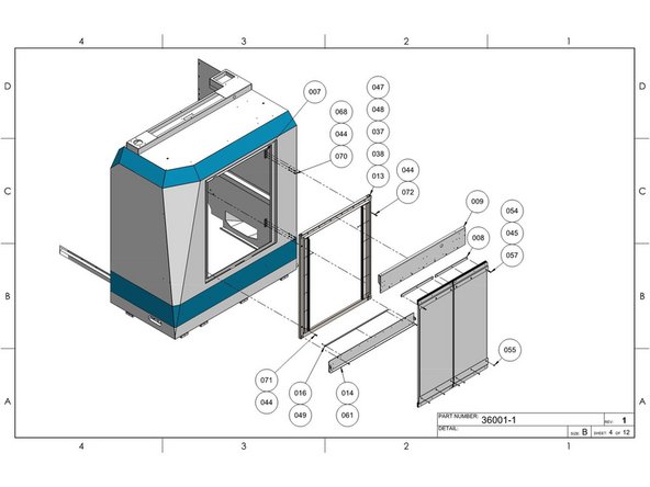
Using drawing 36001-1 pages 3 and 4 for the VMCsi 7/10 machines drill the holes for the remaining sheet metal panels and cable routing clamps. See Image 1.
-
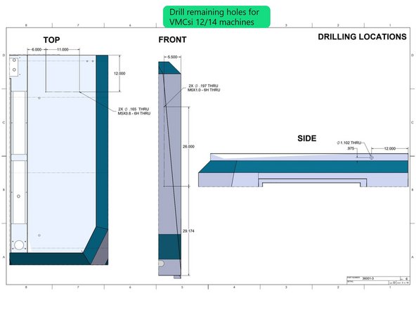
Using drawing 36001-3 page 3 for the VMCsi 12/14 machines drill the holes for the remaining sheet metal panels and cable routing clamps. See Image 2.
-
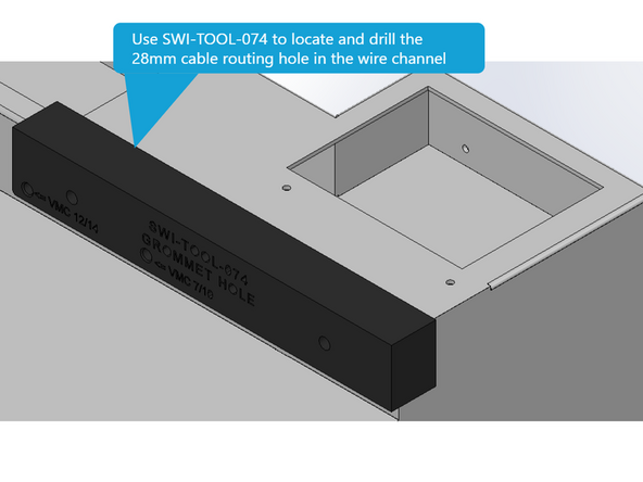
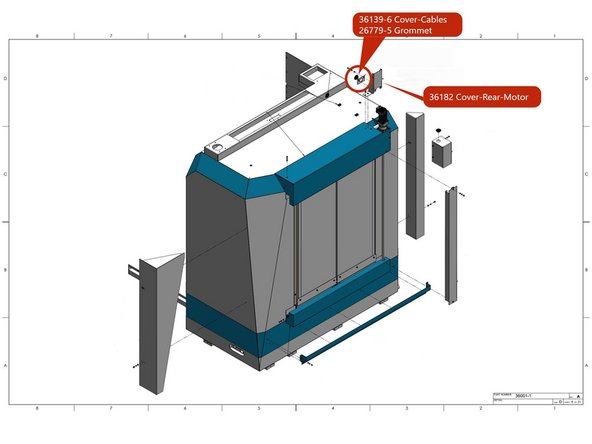
With SWI-TOOL-074 mark and drill the location of the hole in the wire way for the side door motor cables. Once the hole is marked and drilled use a Greenlee Punch or similar tool to open the hole to 28mm in diameter. Once you have made the hole install grommet 26779-5. See Image 3.
-
-
-
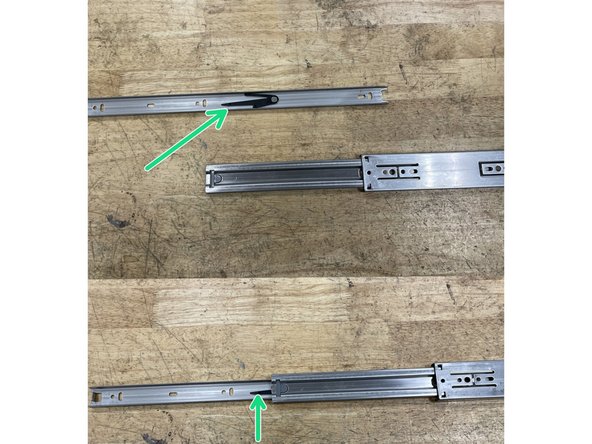
Now install the drawer rails to the mounting plates. Before doing this separate the smaller inner rail from the larger one. Use the black latch in photo 1 to release the inner rail and slide it out of the outer one.
-
Label the removed rail sections and the rails they came out of so when reinstalling them they can be mated back with the rail they came from.
-
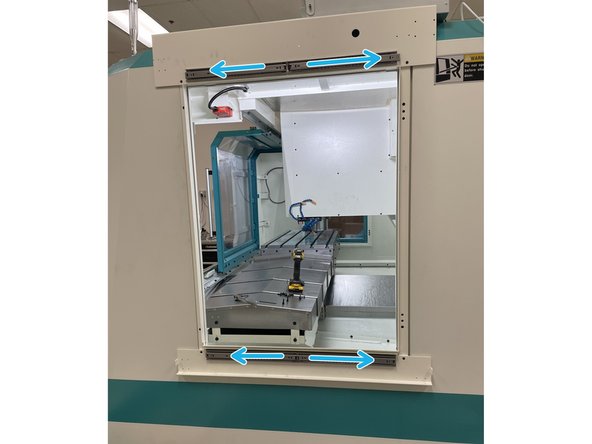
Attach the four(4) drawer rails onto the mounting plates with the rails opening away from the center of the door opening. Leave the drawer rails slightly loose at this time. See photo 2
-
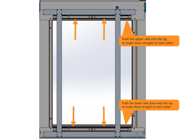
To align the door rails, attach the Alignment Tool SWI-TOOL-077-1 for VMC 7/10 and -2 for VMC 12/14, as shown in image #3. Adjust the upper rails up against the jig and tighten, push the bottom rails down to the jig and tighten. This should make the 2 sets of rails straight and parallel to each other.
-
The smaller rail sections will be installed on the doors in the next 2 steps.
-
-
-
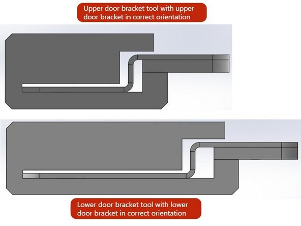
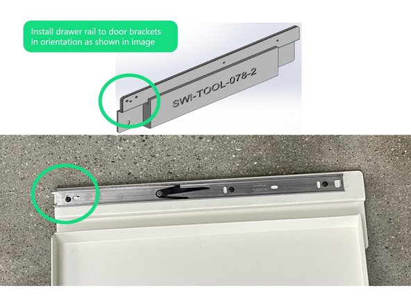
To aid in making the piece of the drawer rails mounted to the doors parallel to the door brackets use SWI-TOOL-078-1 for the top rails and SWI-TOOL-078-2 for the bottom rails. The door brackets need to be installed into the Tool as shown in image 1.
-
Attach the inner drawer rail sections to the doors taking note of where the corresponding rails are mounted on the machine so when the doors are mounted the inner rails will reattach with their mates. Note: Image 2 shows the correct orientation of the rail mounted to the door bracket.
-
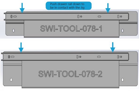
When installing the Drawer Rails to the Door Brackets, the rails should be in contact with the Jigs as shown in image 3.
-
-
-
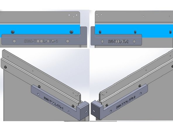
To align the upper Door Brackets to the doors use SWI-TOOL-079-1 for the left side door and SWI-TOOL-079-2 for the right. Place both Jigs onto the flanges of their respective doors see Image 1.
-
Next the Door Brackets need to be in contact with the corner of the Jigs see image 1. Now attach the Door Brackets with the nut plate and M5 screws with flat and serrated washers.
-
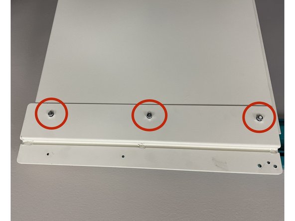
Install the lower Door Brackets to the bottom of the doors and make the M5 nuts with flat and serrated washers slightly loose for now.
-
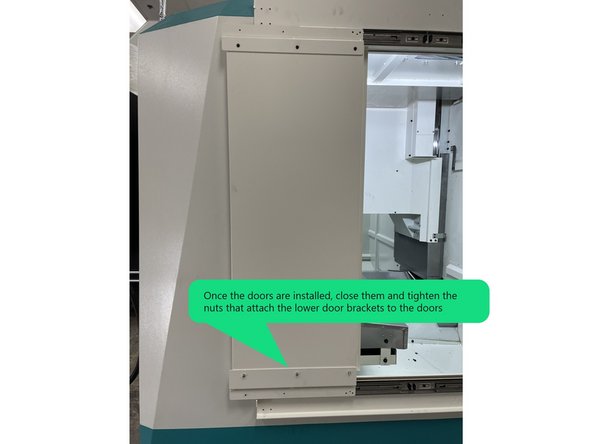
With the Door Brackets attached to the doors Install the right and left side doors to the drawer rails. Once the doors are installed close the doors and tighten the nuts for the Lower Door Brackets.
-
-
-
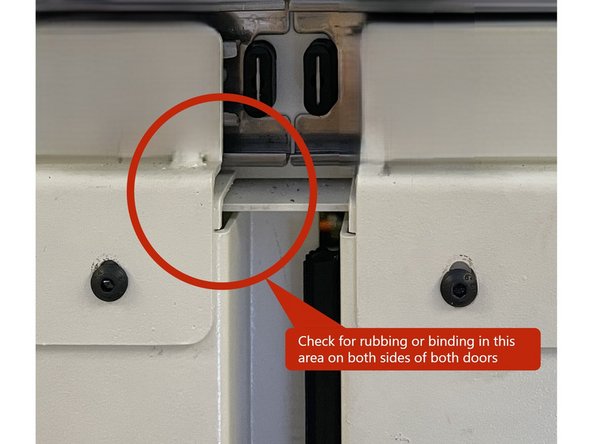
Open and close both doors a few times. They should move full travel with no roughness or binding.
-
If there is some binding or roughness in the movement of the doors check where they go over the lip in the upper rail mounting plate. You may need to adjust the doors up or down to center them over the lip. Check both sides of both doors. Adjust as needed. See Photo 1
-
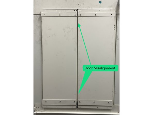
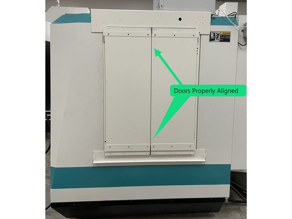
Close both doors all the way and look at how they hang. If there is a larger gap between the doors on either the top or bottom you will need to loosen the door to weldment hardware and adjust one or both of the doors to get them to hang parallel to each other while trying to maintain the height adjustment in the previous step.
-
Photo 2 shows doors misaligned and Photo 3 shows the doors properly aligned.
-
-
-
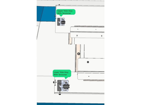
Next install the idler pulley assemblies and tensioners to the left side of the upper and lower rail mounting plates with (4) M5 X 18 SHCS with serrated and flat washers. Then attach the tensioners to the pulleys with an M5X20 Hex head screw. See Photo 1
-
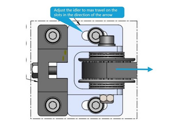
Note: Insure there are no set screws in the idler pulleys Before Installation.
-
Adjust the idlers away from the tensioner to max travel on the slots prior to belt installation. See Photo 2.
-
-
-
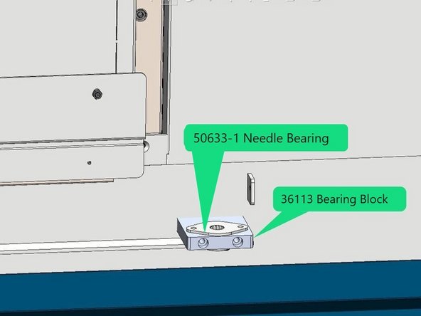
Install the 56033-1 needle bearing to the 36113 bearing block, then install the bearing block to the lower rail mounting plate as shown in photo 1.
-
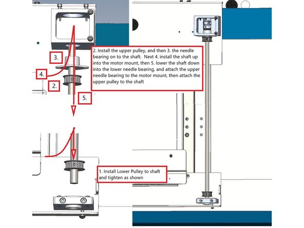
Install the lower pulley 50620-2 onto the flats on the timing shaft 36199 and tighten in place. See Photo 2
-
Install the upper pulley 50620-2 and Needle Bearing 50633-1 to the shaft, and move the shaft up into the motor mount and then lower the shaft into the lower bearing. Next install the upper bearing into the motor mount with (2) M5-0.8 X10 (27B) BHCS then tighten the upper pulley to the flats on the shaft. See Photo 2
-
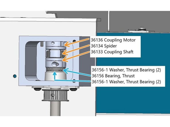
Locate P/N 36156 Bearing Thrust, 36156-1 Washer Bearing Thrust (qty 4), 36133 Coupling Shaft , 36134 Spider, and 36136 Coupling Motor.
-
Install the thrust bearing onto the timing shaft inside of the motor mount with 2 thrust washers on each side of the bearing. See photo 3
-
Now install the Shaft Coupling 36133 to the Timing shaft then install the spider 36134 and then finally the Motor Coupling 36136. See Photo 3
-
-
-
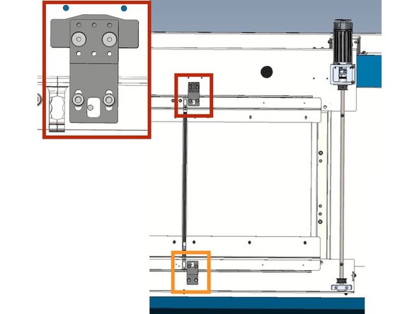
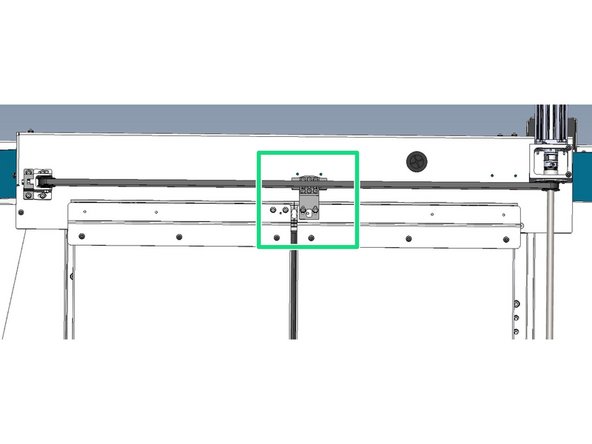
Locate Belt Clamp 36123-1 (qty 2), Plate Belt Clamp 50623 (qty 2) and the Cam Limit Switch 36173 (Qty 1).
-
Attach the Cam-Limit Switch 36173 to the Belt Clamp 36123-1 with(2) M5X14 FHCS. Then attach the 50623 Plate-Belt Clamp using (6) M4X10 SHCS with serrated and flat washers. Then attach the Belt Clamp and Switch Cam Assy to the top of the right door weldment with (2) M5X8 SHCS with flat and serrated washers. See Photo 1
-
Next attach the 50623 Plate Belt Clamp to the 36123-1 Belt Clamp using (6) M4X10 SHCS with serrated and flat washers. Next attach the Assy to the lower door weldment using (2) M5X8 SHCS with flat and serrated washers. See Photo 1
-
Close the right door all the way, then feed the belt (50636) through the idler pulley and around the motor pulley and back to the belt clamp assembly. Run each end of the belt into the center of the clamp and pull belt snug and tighten the screws. Attach both the top and bottom belts. See Photo 2, only top belt shown.
-
If you can't pull the slack from the belt with the pulley at the end of the slots you may need to cut one or two teeth from the belt.
-
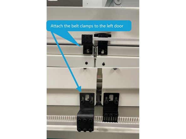
Attach the (2) 36123 Belt Clamps to the left door same as the right. With the right door still closed, close the left door all the way, then attach the Belt Clamp Plates 50623, and Belts to the Belt Clamps using (6) M4X10 SHCS with serrated and flat washers. See Photo 3
-
-
-
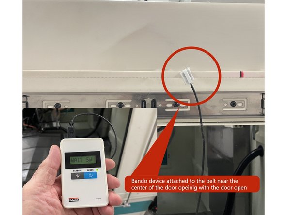
The belt now needs to be tensioned. To do this attach the sensor from the Bando Belt Tension Meter to the belt halfway between the (2) pulleys with the door in the open position. See Photo 1.
-
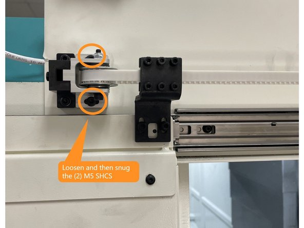
Loosen the two(2 ) M5 screws that mount the idler pulley assy to the base plate and then lightly snug them.
-
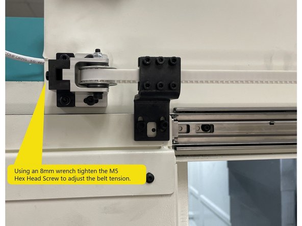
Using an 8mm wrench tighten the belt adjustment screw (M5 Hex Head) until the belt tension reads 50Hz +\- 2Hz on the Bando Meter when the belt is plucked. Then tighten the two(2) M5 screws.
-
-
-
Now you need to align the belt brackets to the pulleys so the belts track correctly. The next few bullet points will show you how to get the belts to track near the center of the pulleys.
-
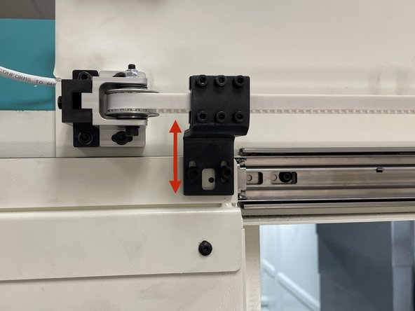
Open the doors all the way, then loosen the left belt bracket and center the belt in the pulley and tighten the screws. Next close the door and adjust the right belt bracket to center the belt in the pulley. Do this for both upper and lower belt brackets. Now open and close the doors to see if the belt tracks in the center of the pulleys.
-
If one or both belts can't be aligned to the right and left pulleys using the belt brackets, loosen the right belt brackets and the pulley on the timing shaft and adjust it up or down to get the belt to track in the center of the pulley. Check both upper and lower belts. Once the belt is tracking correctly tighten the right side belt brackets.
-
After the belts have been adjusted, open and close the doors a few times to verify the belts are tracking near the center of the pulleys. You may need to adjust the pulley up or down a few times to get the belts to track correctly.
-
Once the belt is aligned and tracking correctly recheck the tension to verify it didn't change.
-
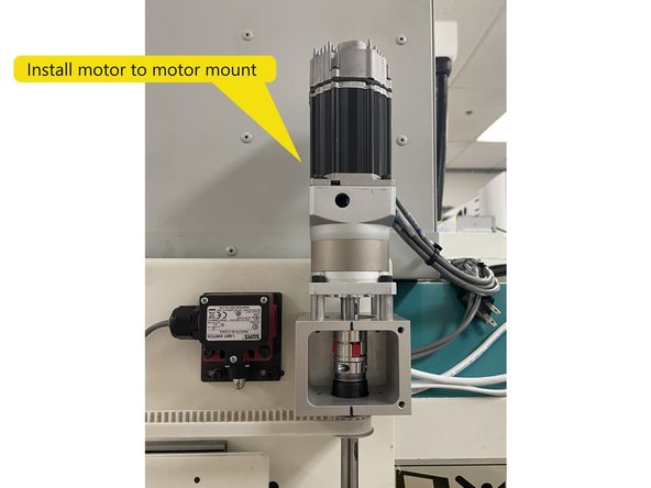
Install the motor with gear reduction and stand offs to the motor mount. Orient with the cables pointing towards the wire way that runs from the pendant to the electrical cabinet. Tighten the Motor coupling to the motor shaft. See Photo 3.
-
May need new photos to show alignment Jig
-
-
-
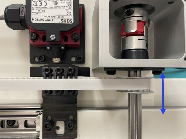
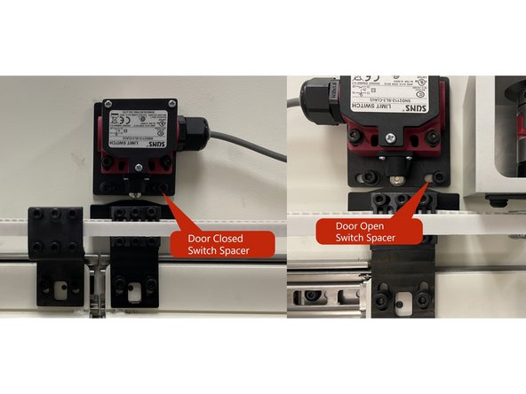
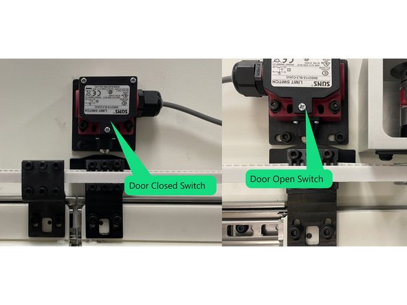
Locate and install the Door open and close switch spacers 36174 (qty 2)to the upper rail mounting plate using (2) M5-0.8 X 12 SHCS with serrated and lock washers per spacer. See Photo 1
-
Mount the Door Closed limit switch 22551-28 to the spacer on the upper rail mounting plate near the center of the door opening. Install the Door Open limit switch 22551-27 to the spacer on the upper rail mounting plate near the motor. Use (2) M4-0.7 X 25 SHCS with serrated and flat washers per limit switch assembly. See Photo 2
-
-
-
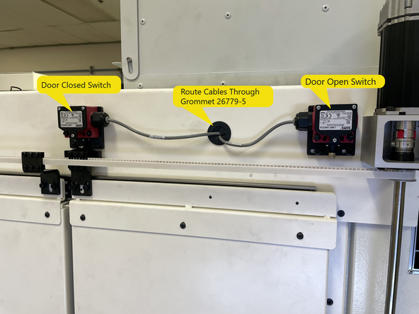
Now that the switches are mounted it is time to adjust them, but before you do route the cables through the grommet in the upper rail mounting plate. See Photo 1
-
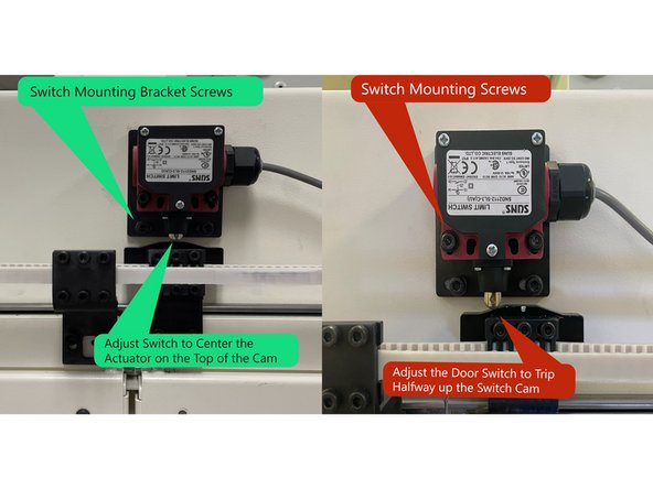
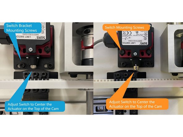
With the doors fully closed align the closed switch so the switch roller is near the center of the switch cam and tighten the switch bracket screws. See Photo 2
-
Next move the door so the switch roller is halfway up the switch cam then adjust the switch up or down so it triggers at this point. Tighten the switch mounting screws. See Photo 2
-
Next open the door all the way and align the open switch so that the switch roller is near the center of the switch cam and tighten the switch bracket screws. See Photo 3
-
Next move the door so the switch roller is halfway up the switch cam then adjust the switch up or down so it triggers at this point. Tighten the switch mounting screws. See Photo 3
-
-
-
Locate cables 29032-248 Side Door Motor Power and 34239-2 Side Door Motor Output Enable/ Side Door Motor Input B/ Side Door Motor Feedback. Attach both cables to the motor.
-
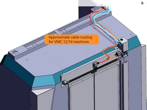
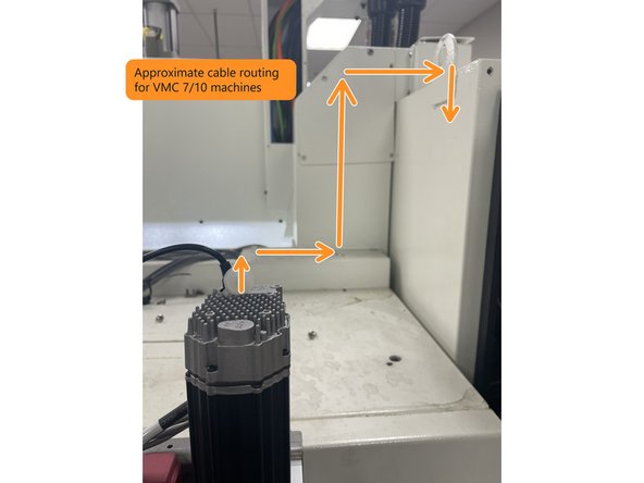
Assemble Cover-Cables (36139-6), Grommet (26779-5) and Cover-Rear-Motor (36182). Run the (2) motor cables and the (2) Limit Switch cables through the Grommet and route back to the electrical cabinet.
-
Image 2 shows approximate routing for VMC 12/14 machines and Photo 3 shows VMC 7/10.
-
-
-
Before you start any wiring of the Auto Side Door Option shut off the main power and lock the power out for safety.
-
Verify the Automation Ready Option has been done, if not do it now before the Auto Side Door wiring for the VMC 7/10 machines. On VMC 12/14 machines the "Electrical Kit -E-Stop and Door Relay Outputs" (34247-1) must be installed first then the "Automation Ready Option" (34232-3 VMCsi 12/14) then finally the Auto Side Door Option.
-
Wire the Automatic Side Door Option using Drawing P/N 36001-1 for VMCsi 7/10 or 36001-3 for VMCsi 12/14 machines. VMCsi 12/14 machines also require Kit 34247-1 VMC 7/10 machines do not.
-
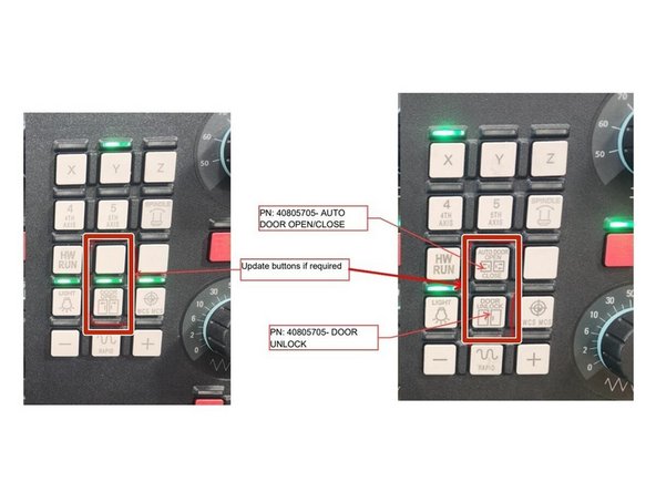
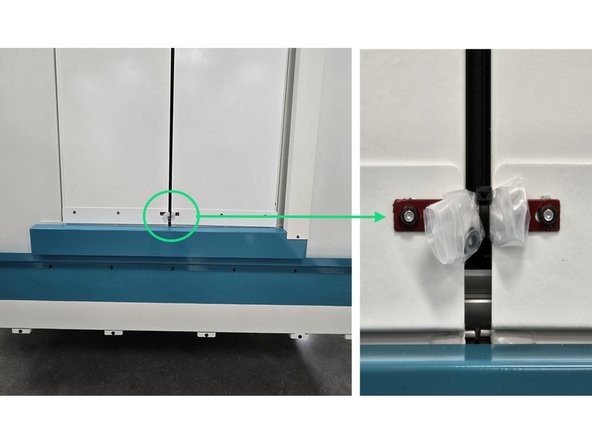
Once the wiring is done update the MCP buttons on the control panel. Remove the existing buttons and install the new ones as shown in Photo 2.
-
-
-
Before the door can be used in automatic mode it needs to be programed.
-
Use the link below to load the Auto Front and Side Door Programing Procedure to assist you in programing the servo drive and motor.
-
-
Once the programing is complete open and close the door a few times and verify you can open and close the side doors with the MCP buttons.
-
-
-
To complete the installation of the Auto Side Door Option you need install the remaining outer sheet metal covers.
-
Using the drawing 36001-1 for VMC 7/10 machines install the remaining sheet metal to the enclosure.
-
Using the drawing 36003-1 for VMC 12/14 machines install the remaining sheet metal to the enclosure.
-
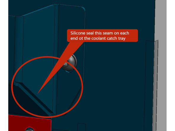
Install the coolant catch tray before you install the Cover-Bottom-Side Door so you have access to silicone it to the cabinet.
-
When installing the coolant catch tray be sure to angle it down towards the rear of the machine where the drain hole is. Then silicone seal it to the cabinet everywhere the coolant catch tray contacts the cabinet and any other points that could leak like the seems at each end.
-
-
-
Remove nuts and washers and install the Auto Side Door lock with nuts. Bag washers and attach to the door lock as shown in Photo 1.
-
Once machine is on the pallet and wrapped, mark the side with the Auto Door with yellow and black caution tape and mark areas that could get damaged if not careful with red paint. See Photo 2
-