Introduction
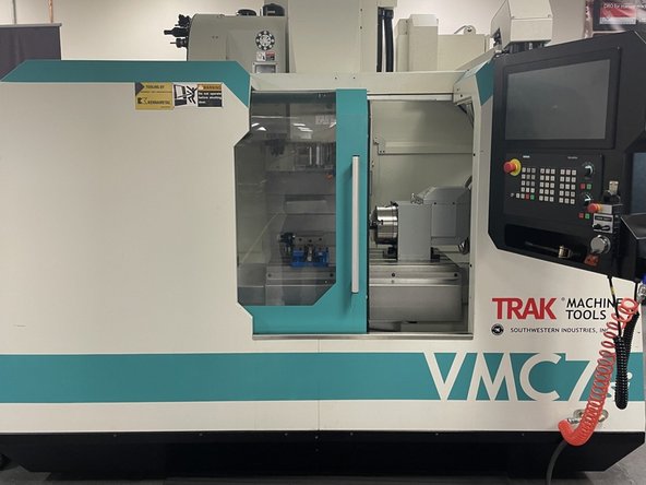
Trak Machine Tools has started offering a series of automation options on our VMCsi series machines, one of them being an automatic front door. With this procedure and drawings 36000-1 (7/10 Series), 36000-3 (12 Series) and 36000-4 (14 Series) you will be able to complete the mechanical and electrical installation and alignment of the Automatic Front door option on the above series machines. The Programing and testing is covered in the Auto Door Programing Guide: https://southwesternindustries.dozuki.co...
-
-
Before we start installing the Auto Front Door Option we want to align the front door so that it tracks straight and level. The next couple of bullet points will show you how to measure and adjust the door to achieve the proper alignment.
-
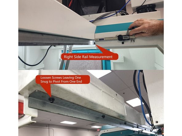
First you want to align the the upper door rail to the upper door support sheet metal. Measure the rail on the right and left side of the door opening from the rail to the front of the door support sheet metal with a Caliper when the door is in the open position. See Photo 1.
-
Loosen the screws on the upper rail leaving one end tight to pivot from and measure and record that end. Verify that it is 5/8"(0.625) ±1/8"(0.125). With that measurement adjust the other end to match that measurement to within ±1/32"(0.0312). See Photo 1.
-
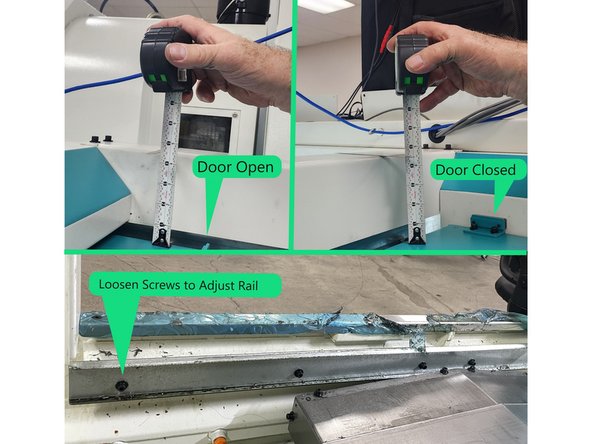
Next measure the height of the door to the top of the upper door support with the door in the open position, record that measurement. Repeat with the door closed. Loosen the screws on the lower door rail leaving one tight to pivot from and adjust the height of the door closed to match the door open height to within 1\16"(0.062). See Photo 2
-
-
-
Once the door has been adjusted you should verify that the door locks when it is closed.
-
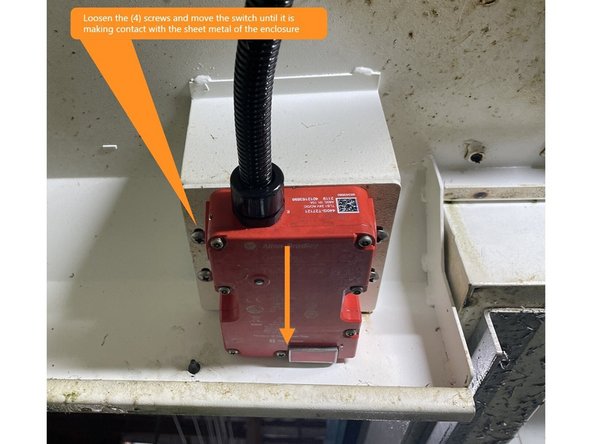
Close the door all the way slowly like the machine will do in automatic mode. Once closed try to reopen the door, it should be locked and not reopen. If the door reopens, loosen the four (4) mounting screws and adjust the switch so that it is making contact with the sheet metal of the enclosure. See Photo 1
-
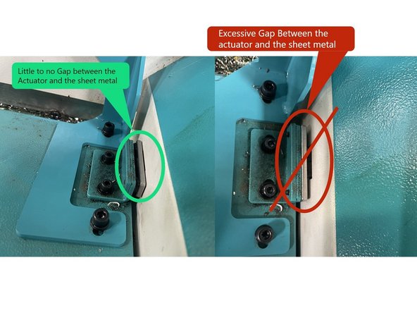
If the door still doesn't lock check the actuator, there should be little to no gap between the switch actuator and the cabinet sheet metal. You may need to put a washer or two between the actuator and the actuator mounting bracket to get the door to lock. See Photo 2
-
-
-
Once the door has been aligned we want to measure the force required to release the door from the latches at each end of the door (Breakaway Torque), and the force required to move the door in between the latches (Rolling Torque). We use a fish scale to make these measurements.
-
To close the door from the open door latch it should require about 10-12 lbs of force to break away from the latch, and once it has broken away from the latch it should take 2-3 lbs of force to move between the latches. To open the door it should require the same breakaway and rolling torque force as to close it.
-
These values will be used as a baseline. If these values change once the auto door is installed, that may mean that there is a mechanical misalignment problem.
-
-
-
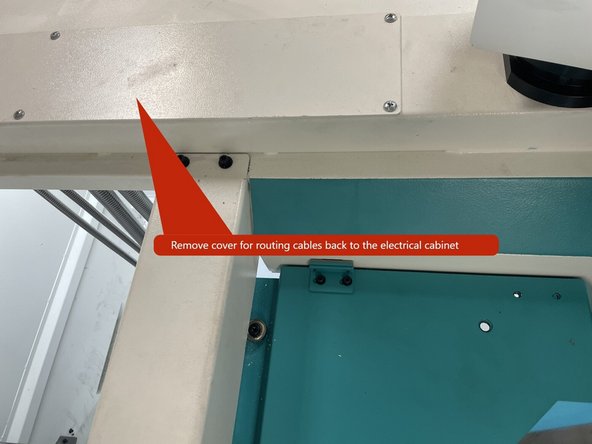
To get started with the Auto Front Door Installation you need to remove the cover from the wire channel on the upper right side of the cabinet so the wiring for the motor and Home/Limit switch can be routed back to the electrical cabinet.
-
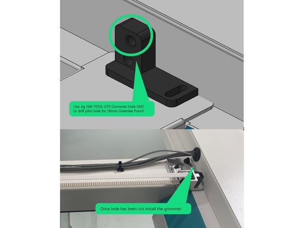
Using Jig SWI-TOOL-070 Mark the pilot hole for the Greenlee punch or similar device to make the grommet hole in the wire channel on the upper right side of the main cabinet. Use a 28 mm (1.102")Greenlee punch or similar device to make the hole. Install the 28mm grommet(26779-5) that the motor and home switch cables route through. See Photo 2.
-
Use existing hardware to mount Jig SWI-TOOL-070 to mark hole in wire channel.
-
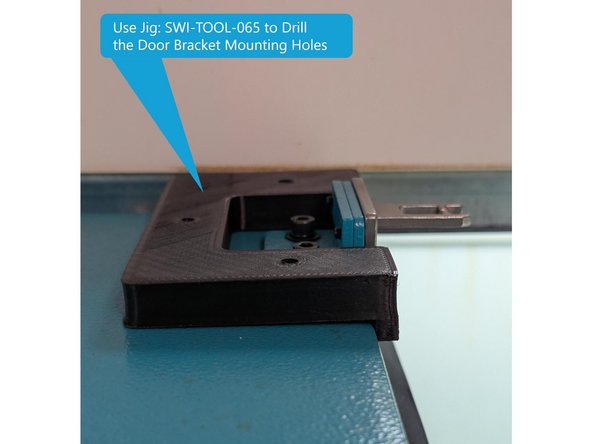
Once the door has been aligned, use jig (SWI-TOOL-065) to mark/center punch the mounting holes for the door bracket. Drill the holes clearance for M6 socket head cap screws (7mm Drill bit). See Photo 3
-
-
-
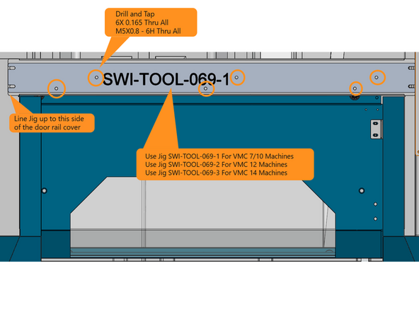
Next using Jig SWI-TOOL-069-1 for VMC 7/10, SWI-TOOL-069-2 for VMC12, or SWI-TOOL-069-3 for VMC 14 machines, drill and tap the 3 holes used to mount the brush, and the 3 holes for mounting the cable tie holders for the motor and switch cables. Drill all holes 0.165" and tap M5. See photo 1
-
Use existing hardware to mount Jig SWI-TOOL-069- 1, -2 or -3 to mark holes in upper door support bracket. Line Jig up to the left side of the door rail cover
-
-
-
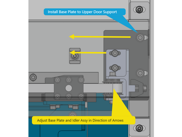
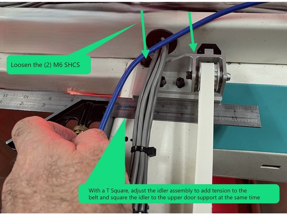
Attach the base plate and idler pulley assembly to the enclosure on the right side of the upper door support bracket with (2) M6X20 SHCS with flat and serrated washers (remove existing screws and replace with above hardware). See Photo 1.
-
Adjust the idler and base plate assembly on the slots of the M6 screws all the way to the left (in direction of arrows in photo), do the same with the idler pulley bracket on the M5 screws. See photo 1.
-
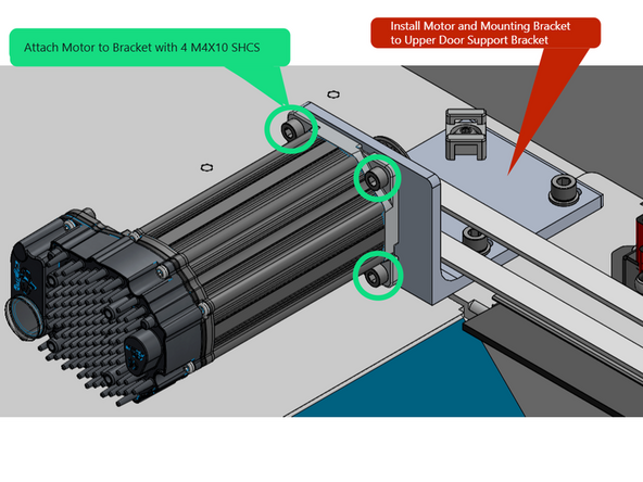
Locate the motor mounting bracket P/N 36144 and install the motor to it with four(4) M4X10 SHCS, then install the key and pulley to the motor shaft and tighten the 2 set screws in the pulley to the flats on the motor shaft. See Photo 2
-
Next install the motor assembly to the machine enclosure on the left side of the door support bracket with two(2) M6X20 SHCS with flat and serrated washers (remove existing screws and replace with above hardware). See Photo 2
-
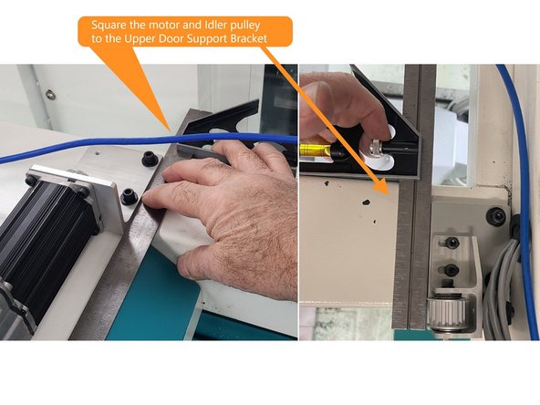
Using a T-Square, Square both the motor and idler pulley to the Upper Door Support Bracket and tighten the screws. See Photo 3
-
-
-
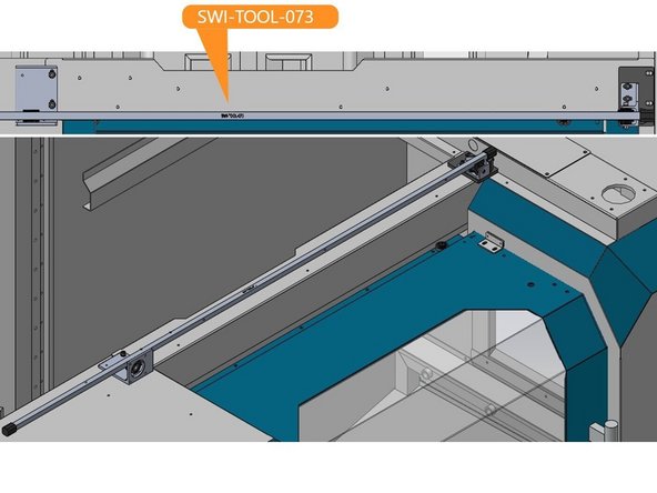
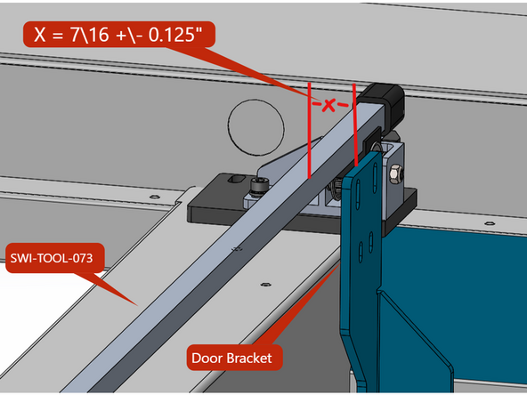
Install SWI-TOOL-073 Pulley Alignment Jig to the pulleys as shown in Photo 2. Loosen the screws on the motor and the idler pulley and snug the idler pulley screws using the idler pulley as a pivot point.
-
Install Door Bracket to Door.
-
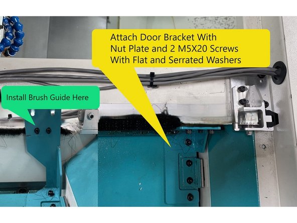
Before you install the door bracket to the door attach the Brush Guide P/N 36149 to the Door Bracket P/N 36148-3 with two(2) M4X8 SHCS with flat washers. See Photo 2
-
Attach the Door Bracket to the door using the Nut Plate P/N 36150 and two(2) M6X20 SHCS with serrated and flat washers. See Photo 2
-
With the door closed, align the door bracket to the Pulley Alignment Jig, SWI-TOOL-073, to 7/16"(0.4375") ±1/8" (0.125"), where 7\16" is X in photo 3. Record that number.
-
Then open the door and adjust the motor so that the distance from the Jig to the Door Bracket matches the number you recorded on the idler pulley side. You may need to go back and forth a few times to get the numbers to match within 0.030".
-
-
-
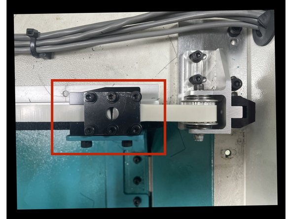
Install Clamp-Base-Belt (36142) to the belt bracket an mount the Plate-Belt Clamp-XL (33309) to it with (6) M4-0.7X16 (25B) SHCS. See Photo 1
-
Feed the belt through the idler pulley, around the motor pulley and back to the belt clamp. Belt clamp should be on upper side of belt. Pull the belt snug in the clamp and tighten the M4 screws. You may need to cut one or two teeth from the belt to minimize the slack in the belt when installed. See Photo 2
-
Loosen the 2 M6X16 SHCS in the idler base plate assembly. Using a T Square push the idler base plate to the right to remove any slack in the belt and square the Idler base assembly to the upper door support sheet metal at the same time . See photo 3.
-
-
-
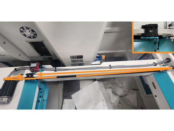
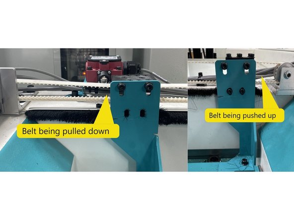
For belt alignment, open the door and check the belt height coming off the motor pulley, close door and check the idler pulley as well. If the belt is being pulled up or down close the door and loosen the belt clamp to belt bracket mounting screws and align the belt so it's coming straight off of the idler pulley. Recheck the open position again.
-
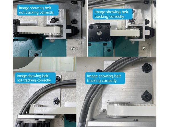
Next open and close the door a few times to see if the belt is tracking in the center of the pulleys. If not loosen the motor bracket screws and adjust the motor bracket so that the belt is centered in both pulleys when opening and closing the door.
-
You may need to go back and forth a few times to get the belt to track in the center of the pulleys.
-
You may also need to loosen the (6) M4 screws that clamp the belt if the belt isn't held straight in the belt clamp, straighten the belt and and then tighten the screws.
-
Open and close the door a few times to verify the belt is tracking correctly, if it is verify the belt clamp bracket screws, idler pulley screws and motor screws are tight.
-
-
-
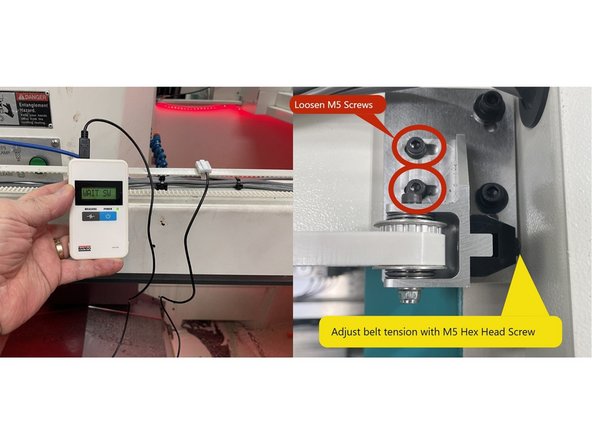
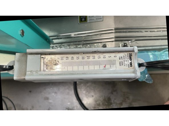
The belt now needs to be tensioned. To do this loosen the two(2 ) M5 screws that mount the idler pulley assy to the base plate and then lightly snug them. Next attach the sensor from the Bando Belt Tension Meter to the belt halfway between the (2) pulleys with the door in the open position. See Photo 1.
-
Using an 8mm open end wrench tighten the belt adjustment screw (M5 Hex Head) until the belt tension reads 50Hz ±2Hz on the Bando Meter when the belt is plucked. Then tighten the two(2) M5 screws.
-
Now that the Auto Front Door Option has been installed and the belt aligned and tensioned we once again measure the force required to open and close the door using a fish scale.
-
The force to move the door from the open/closed latches should be about the same as after the door was aligned in step 1, 10-12 lbs of force to exit the latches (breakaway) and 2-3 lbs to open/close the rest of the way (rolling torque).
-
If the door requires more than the above breakaway or rolling torque values, verify the motor is square to the Upper Door Mounting Bracket, check the Door Bracket alignment, and the belt tension.
-
-
-
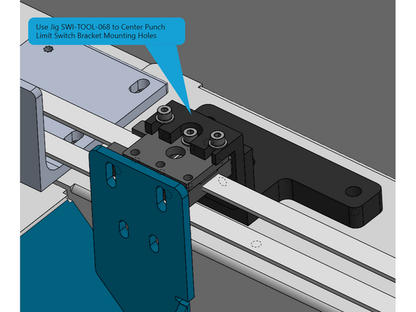
Next you need to install the Home/Limit switch. Using Jig P/N SWI-TOOL-068, open the door all the way and install the Jig to the door bracket. Now with a center punch mark the hole locations through the bushings in the Jig. Finally drill and tap the holes for an M5X0.8 6H thread.
-
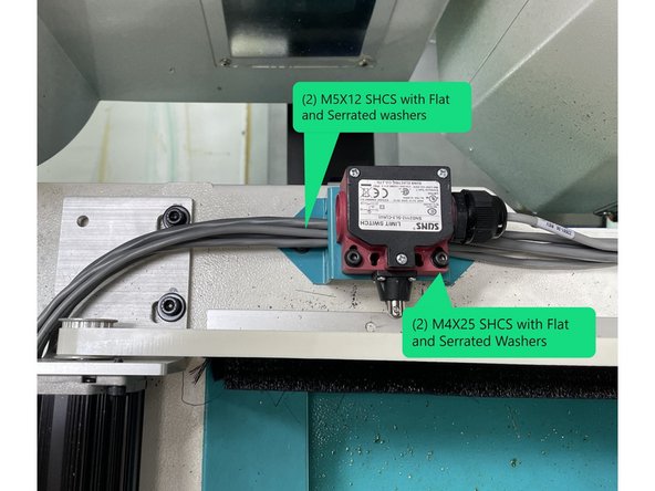
Install Home/Limit Switch P/N 22551-26 to the Home/Limit Switch Bracket P/N 36167 with (2) M4X25 SHCS and flat washers. Then attach the switch and bracket to the Upper Door Support Sheet Metal using (2) M5X12 SHCS with serrated and flat washers as shown in Photo 2.
-
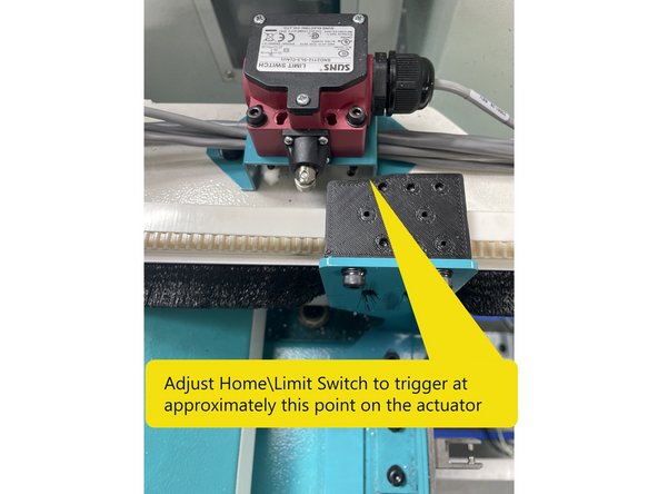
Adjust the switch so that it triggers at about the mid point of the switch actuator on the belt clamp bracket. See Photo 3
-
-
-
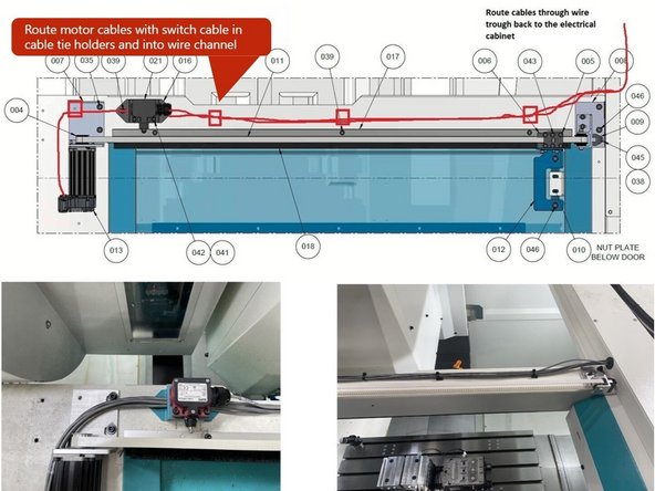
Next connect the Motor Power and Signal cables to the motor. Route through the limit switch bracket and join them with the Home/Limit switch cable and tie them all into the cable tie holders and run them back to the wire channel and into the electrical cabinet. See Diagram 1.
-
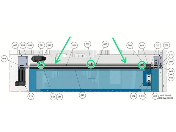
Next install the Brush P/N 36169 and Brush Holder P/N 36168-1 to the machine with (3) M5-0.8X12 SHCS so that the brush is under the door drive belt. (Locations circled in green in Photo 2)
-
-
-
Before you start any wiring of the Auto Front Door Option shut off the main power and lock the power out for safety.
-
To install the electrical wiring refer to Drawing 36000-1 for VMCsi 7/10 machines and 36000-3 for VMCsi 12/14 machines.
-
Note: Auto door installation drawing for the VMCsi14 is 36000-4 but the wiring information is found on drawing 36000-3
-
-
-
Before the door can be used in automatic mode it needs to be programed.
-
Use the link below to load the Auto Front and Side Door Programing Procedure to assist you in programing the servo drive and motor.
-
Auto Door Programing Guide: https://southwesternindustries.dozuki.co...
-
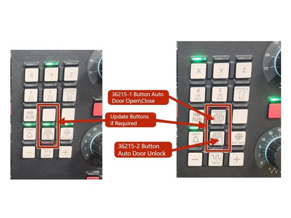
Once the programming is done update the MCP buttons on the control panel. Remove the existing buttons and install the new ones as shown in Photo 2.
-
Once the programing is complete open and close the door a few times and verify you can unlock and open and close the door with the MCP buttons.
-
-
-
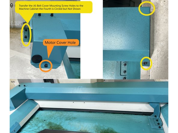
Install the belt cover and transfer the mounting hole locations from the cover to the top of the machine sheet metal. Then drill and tap them M5X0.8 6H. See Photo 1
-
Next install the motor cover and transfer the one hole and drill and tap it M5X0.8 6H. See Photo 1
-
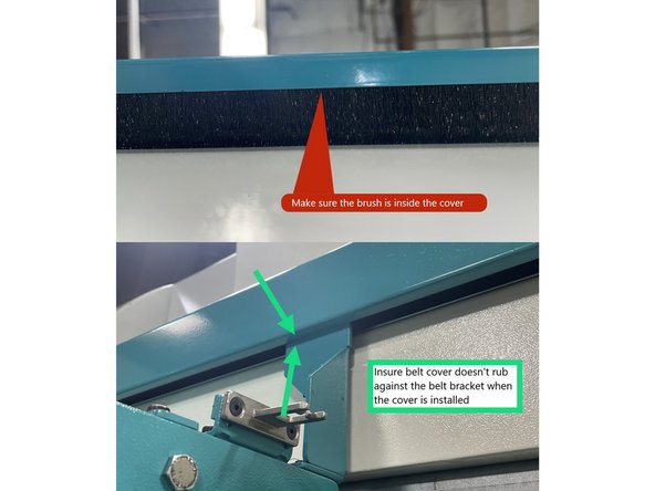
Now install the belt cover and verify that the end of the brush is inside of the cover, if not remove the cover, adjust the brush and reinstall the cover. See Photo 2
-
Verify the belt cover doesn't rub against the door bracket when installed. When the cover is aligned correctly tighten the screws. See Photo 2.
-
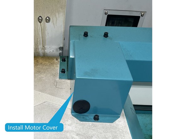
Finally install the motor cover, and clean machine. This completes the Auto Front Door installation.
-