-
-
If the Trunnion is not enabled, follow the procedure on the [TrakMT Options] screen.
-
[Setup] → [TrakMT Options]
-
If the trunnion is being installed or its bolts are loose:
-
Position the trunnion in the correct mounting location.
-
Hand tighten the main mounting bolts so the trunnion is secured but still adjustable.
-
Lightly snug the adjustment block to hold position without fully locking it.
-
-
-
Set the X-Axis to 12 o’clock and reset the A-Axis to 0.
-
Position the dial indicator ¼” from the back edge of the platter using the Y-Axis.
-
Using the Z-Axis in fine increments, preload the indicator to 0.004”, then set the dial pointer to 0.
-
Move the Y-Axis toward 6 o’clock until the indicator is ¼” from the near edge of the platter.
-
Check the dial indicator readings at the 12 o’clock and 6 o’clock positions:
-
If both readings are 0 and the A-axis display on the control panel reads 0.000°, skip to Step 5 (the A-axis is already referenced correctly).
-
If they differ, proceed to Step 3.
-
-
-
Tilt the A-axis in fine increments until the dial indicator is midway between the start and end readings.
-
For example, if the start reading is 0 and the end reading is 0.002”, adjust the A-axis until the indicator reads 0.001”.
-
Reset the dial indicator to 0 and move the Y-axis back to 12 o’clock on the rotary table.
-
Check if the dial indicator still reads 0 (or within 0.0001”).
-
If the readings at both 12 o’clock and 6 o’clock are 0, the A-Axis zero position is found.
-
To set this position as the new 0, proceed to Step 4 for A-Axis referencing.
-
-
-
Step 4 is required only if you are adjusting and found 4th-Axis zero position from Step 3.
-
-
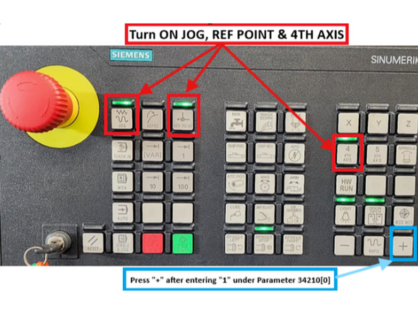
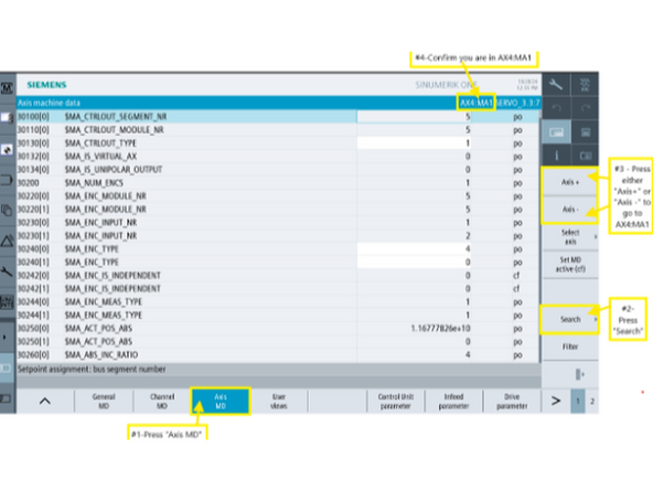
Go to [Setup]→ [Mach. data] → [Axis MD] → [Select Axis] →[AX4:MA1] → [Search] for 34210.
-
Turn on the [JOG], [REF. POINT], and [4th Axis] buttons on the MCP.
-
Change Parameter 34210 to "1"
-
Press the "[+]" button on the MCP. The value for Parameter 34210[0] should change from "1" to "2" automatically.
-
The changing of the value to "2" means that the referencing process is complete.
-
For Reference: VMCsi - Reset Machine Absolute Zero for Each Axis
-
-
-
Move the dial indicator to 3 o’clock on the platter, positioning it ¼” from the edge.
-
Preload the indicator to 0.004” and set the dial pointer to 0.
-
Sweep the X-axis from 3 o’clock to 9 o’clock across the platter.
-
Observe the indicator reading at 9 o’clock to determine if deviation exceeds 0.0008”.
-
If adjustment is required, loosen the cradle support bolts on the high side to lower the cradle into the correct position.
-
If that does not correct the issue, shim the trunnion on the low side using twice the measured difference. After shimming, restart the process from Step 2.
-
-
-
Move A-axis to 0.000° (flat), mount a dial indicator to the spindle, and preload it on one edge of the platter slot.
-
Jog the X-axis across the slot (right to left) and rotate the C-axis until both ends read the same value. Record this C-axis position.
-
Tilt the A-axis to +90° or -90° (depending on Trunnion orientation) and repeat to obtain a second C-axis value.
-
Reverse the sign of both values, e.g., 0.082 → (–0.082), then calculate their average.
-
Go to [Setup]→ [Mach. data] → [Axis MD] → [Select Axis] →[AX5:MC1] → [Search] for 34090[0].
-
If 34090[0] is 0.000, enter the averaged result directly.
-
If 34090[0] already contains a value, subtract the old value from the new averaged result and enter that correction.
-
Press [Reset PO] to apply the new reference offset.
-
-
-
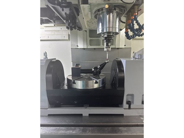
Tilt the A-axis to +90° or -90°, depending on the Trunnion’s orientation along the X-axis.
-
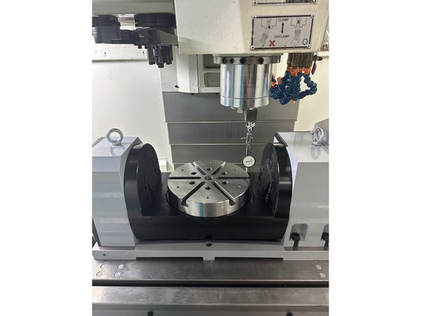
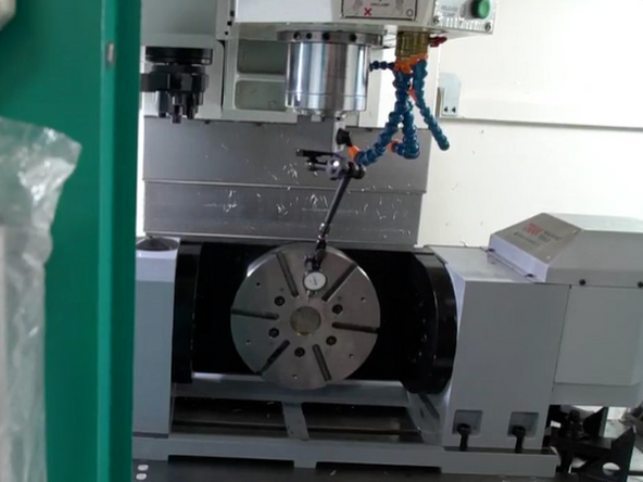
Set up the dial indicator as shown in the image.
-
In JOG mode, move the X and Z axes to position the indicator pointer vertically at the centerline of the rotary table, ¼” from the rightmost edge (3 o’clock position).
-
Slowly move the Y-axis to preload the indicator to 0.004”, then set the dial to zero.
-
Move the X-axis to the opposite (9 o’clock) side of the rotary table.
-
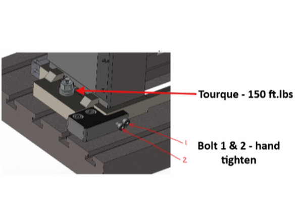
If the readings differ, loosen the left clamp and adjust the left side of the assembly along Y to correct.
-
Use adjustment screws 1 and 2 to fine-tune until deviation is ≤ 0.0001”.
-
Once aligned, tighten all clamps and torque both anchor blocks to 150 ft.lbs.
-
-
-
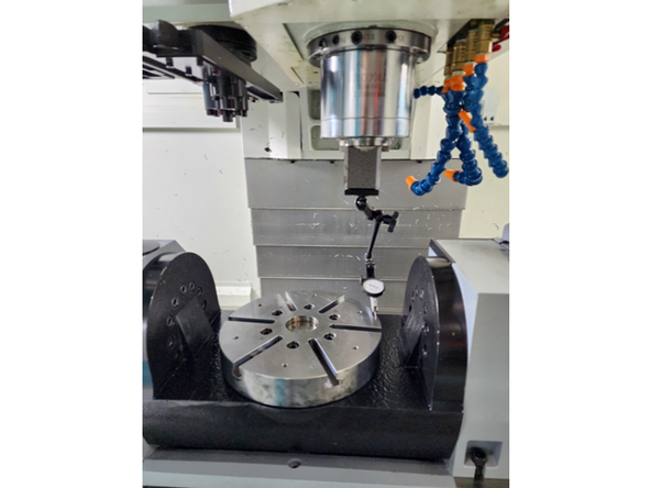
Position the dial gauge pointer as shown in the image.
-
Preload the indicator to 0.004” and set the dial pointer to 0.
-
Slowly rotate the platter 360 degrees, observing the + and - variations from zero.
-
Calculate the Total Indicator Reading (TIR) by finding the difference between the maximum and minimum values.
-
Ensure TIR does not exceed 0.002”.
-
If readings exceed the limit, inspect the platter mounting surface and flatness.
-
-
-
Continue to Trunnion Calibration
-
![If the Trunnion is not enabled, follow the procedure on the [TrakMT Options] screen.](https://d3t0tbmlie281e.cloudfront.net/igi/trakmtsupport/5WGr2HRMs5GZqnMr.medium)