-
-
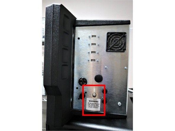
Make sure the main power is turned off on the back of the electrical cabinet before plugging in the cables.
-
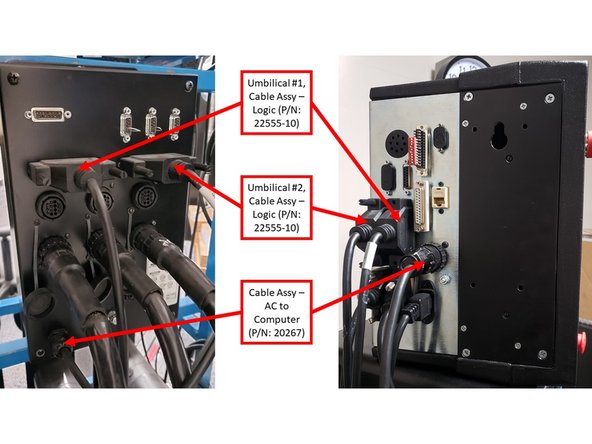
With the main power to the machine turned off, check all connectors that are bundled on the pendant (P/N: 24000-1) arm. Each cable mates to only one connector on the pendant display back panel. Please see first image on the left for a breakdown of the connectors on the pendant arm side.
-
Use the key that is located on the back of the pendant to match up the connectors with the correct ports.
-
-
-
The Cable Breakout Box (P/N: 24999) is located on the back side of the machine. On machines without the auxiliary function option, it consists of three (3) motor connections, three (3) limit switch connections, three (3) encoder connections and an E-stop connection. Please see first image on the left for a breakdown of the connectors.
-
Machines with an auxiliary function option have two (2) more outlets. A 110 V outlet for a coolant pump or air solenoid and an indexer outlet. See second image on the left for more information.
-
The coolant pump signal and indexer signal comes down from Umbilical #2.
-
-
-
There is a total of four (4) cables that need to be connected to the pendant for non-spindle control machines:
-
The following three (3) cables must connect from the Pendant to the Cable Breakout Box: Umbilical #1 (P/N: 22555-10) and #2 (P/N: 22555-10) cables, and AC to Computer (P/N: 20267) cable. Please see first image on the left for more information.
-
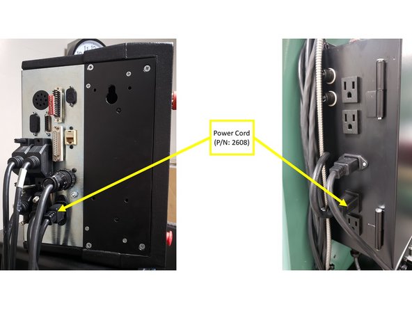
The Power Cord (P/N: 22608) must connect from the Pendant to the Electrical Box. Please see second image on the left for more information.
-
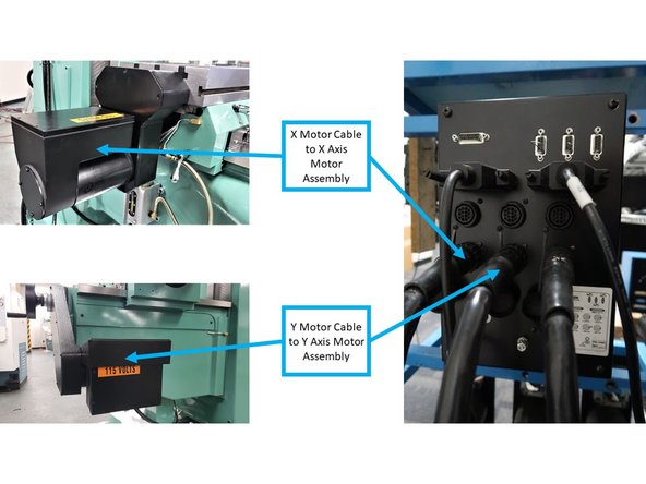
Connect the X and Y Motor Cables to the X and Y Motor Assemblies (P/N: 20296), as shown on the third image on the left.
-
-
-
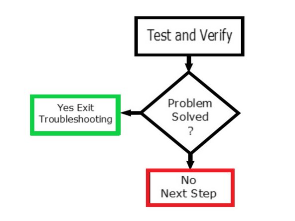
After checking all of the electrical connections, restart and recheck to see if problem still exists.
-
If the problem is solved, exit troubleshooting.
-
If the problem is not solved, go to next step.
-
-
-
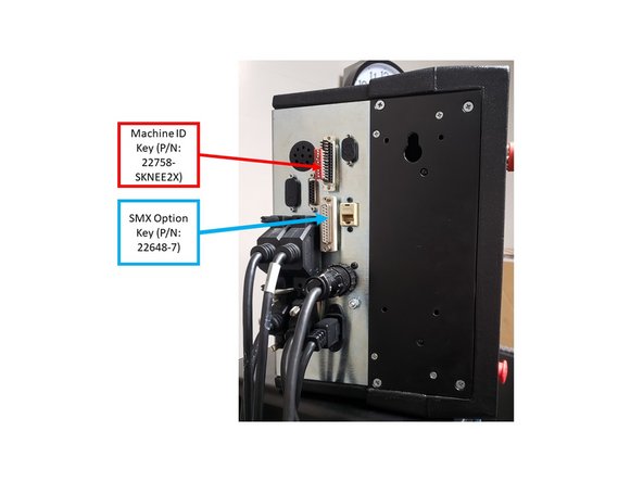
The machine ID port (or called LPT) and parallel port (hardware key) will have a key plugged into it.
-
Make sure that the Machine ID Key (P/N: 22758-SKNEE2X) is plugged into the machine or it will not run. Spindle control machines use a different Machine ID Key than non-spindle control machines.
-
Make sure that there is a Hardware (Option) Key (P/N: 22648) plugged into the parallel port of the pendant. This key activates any converters or options ordered. The key must be programmed according to the type of machine it is on, and the options ordered.
-
-
-
After Checking the connections of both Keys, reboot and recheck to see if problem still exists.
-
If the problem is solved, exit troubleshooting.
-
If the problem is not solved, go to next step.
-
-
-
Turn off and unplug the system from the wall.
-
Do not plug and unplug connectors with the system power on. This may cause damage to the connector board, and harm to the technician.
-
Visually inspect the connections for excessive debris, moisture, or obvious damage.
-
Carefully clean any chips away from the connectors.
-
One-by-one take out each connector, check all the pins on the connector to make sure they are ok (not damaged) and then plug them back in. Do the same at the computer/display.
-
Make sure to tighten up the screws on each of the connectors.
-
Whenever you replace a cable or reroute a cable, it is very important to keep the power cables and logic cables separated from each other. Mixing of the power and logic cables may cause noise from the power cables to interrupt the signals in the logic cables. This can lead to intermittent axis faults or repeatability problems.
-
-
-
After Checking the connections of the cables, reboot and recheck to see if problem still exists.
-
If the problem is solved, exit troubleshooting.
-
If the problem is not solved, go to next step.
-
-
-
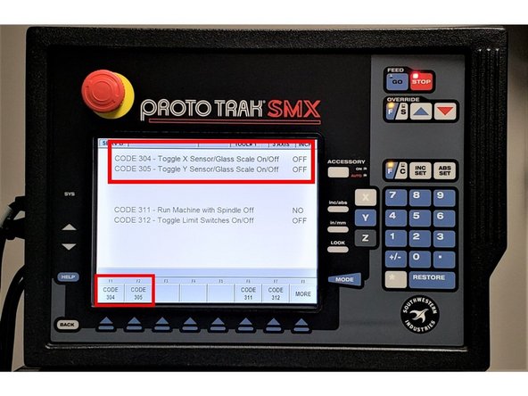
If the Knee Mill with the Run Away Axis issue contains secondary feedback devices such as the the glass scales and/or TRAK sensors, you must also take them into consideration as possible sources for Run Away Axis.
-
Turn off these secondary feedback devices by running Service Codes 304 (which toggles the X sensor or glass scale on/off) and 305 (which toggles Y sensor or glass scale on/off).
-
If the Run Away Axis no longer occurs when either the glass scales and/or sensors had been turned off, then these secondary devices are likely the sources of the problem.
-
If the Run Away Axis continues to be an issue with these secondary feedback devices off, then proceed with the following step regarding physically switching the X and Y Motor Cables.
-
You must turn off the glass scales and/or TRAK sensors prior to switching the X and Y Motor Cables on the Cable Breakout Box!
-
-
-
After disabling the glass scales and/or sensors, reboot and recheck to see if problem still exists.
-
If the machine is working properly, exit this guide and checkout the glass scales and/or TRAK sensors.
-
If the problem still exists, go to the next step.
-
-
-
You must turn off the glass scales and/or TRAK sensors prior to switching the X and Y Motor Cables on the Cable Breakout Box!
-
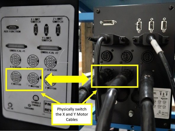
Pinpoint the source of the Run Away Axis issue by swapping the problematic motor with a known good motor.
-
Turn off the power on the control before proceeding with the next steps.
-
For example, if the Run Away Axis issue occurs on the X-Axis, physically switch the X and Y motor cables on the Cable Breakout Box to pinpoint the source of the issue.
-
If the Run Away Axis issue moves to the Y-Axis as a result of the motor cables being switched, then the issue itself may be caused by a bad motor, and the motor must be replaced.
-
Physically Switch the X and Y Motors
-
Rarely do both the X and Y motor/servo systems fail at the same time and in the same way. So, if the problem occurs on both axes, its source is probably somewhere else.
-
-
-
Reboot and recheck to see if problem still exists.
-
If the problem switched axis, you have a bad motor and cable. The unit motor and cable unit should be replaced. Exit Troubleshooting.
-
If switching the cables shows no change on the machine, go to next step.
-
-
-
Umbilical cables go from the break out box to the axis and can flex a lot over the years. It is common to find an internal break that is not serviceable. Troubleshooting these cables for a problem means replacement of the cable with a new one.
-
Bed Mills and Lathes both use these cables. They can attach to the rear of the pendant with the exposed wire jacket or travel through an enclosed pendant arm. They need to be reinstalled just like the factory installation which may involve clips, tie bands, etc.
-
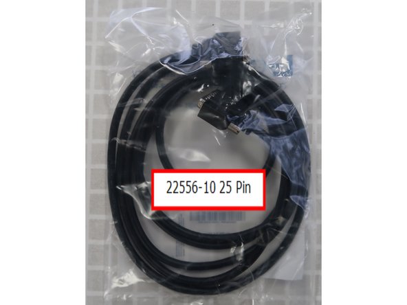
There are two types of Umbilical cables, 25 pin and 37 pin. We stock different lengths based upon mill design. Item shown is part number 22556-10, a 25 pin cable 10 feet long. The 25 pin cable also comes in a 25 foot length.
-
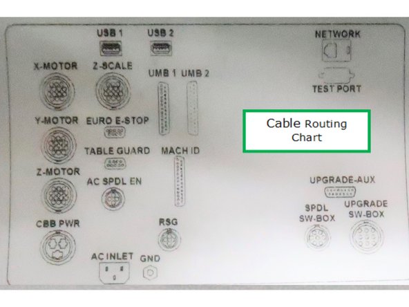
Carefully trace the wire needed for the cable you are replacing. There are many moving parts on the mill and the cables are routed for a reason from the factory. You likely will have to cut and replace zip ties to secure the cables properly. Mills have diagrams showing the correct connection locations on the pendant and breakout box.
-
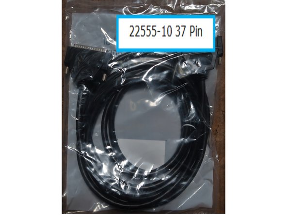
Part number 22555 is a 37 pin umbilical cable that comes in 10, 15, and 25 foot lengths. Photo shows a 22555-10, a 37 pin cable 10 feet long.
-
Replace one of the two Umbilical cables for now. Note which cable is being replaced; Z Axis cable or X-Y Axis cable. In case the first cable does not solve the problem, you will return to this step and check the other cable.
-
-
-
After installing the new Umbilical cable, reboot and recheck to see if problem still exists.
-
If the new cable has cleared the run away axis, exit trouble shooting.
-
If the problem still exists, repeat the previous step with the other Umbilical cable.
-
If both cables have tested ok, next step.
-
-
-
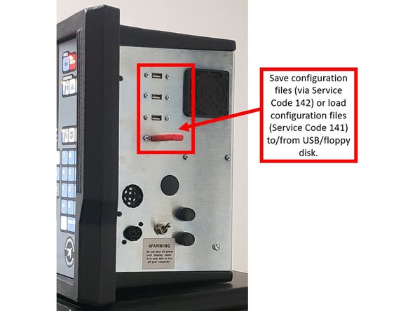
If applicable, save the configuration file from the computer and save to a floppy disk or external drive.
-
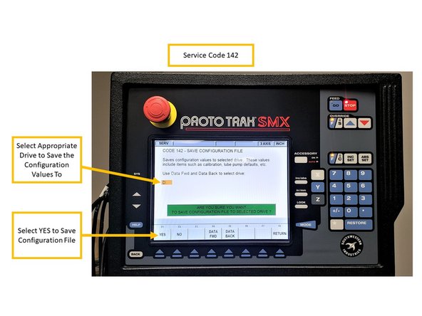
Service Code 142 allows you to save your configuration file to a floppy disk or external drive. The configuration file consists of items such as calibration and backlash constants. This code is used when a computer module or hard drive needs to be replaced. This stores the configuration file from the hard drive to the floppy disk.
-
Insert USB/floppy drive on the SX control. On the Service Code 142 screen, select the appropriate drive to save the configuration files to (D Drive will be available for most USBs), and choose YES.
-
Turn off power to the machine and control.
-
-
-
Unplug all the connectors on the pendant arm side of the pendant.
-
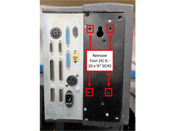
Remove the pendant from the pendant arm by removing the four (4) 1/4 - 20 x 3/4" SCHS that secure it in place.
-
-
-
Place pendant assembly on a clean and secured table with the display pointing away from you.
-
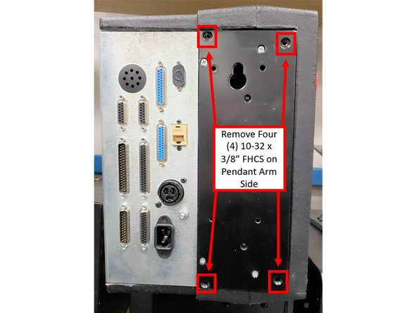
Remove four (4) 10-32 x 3/8" FHCS from the pendant arm side of the SX Pendant that are securing the computer module to the LCD/enclosure.
-
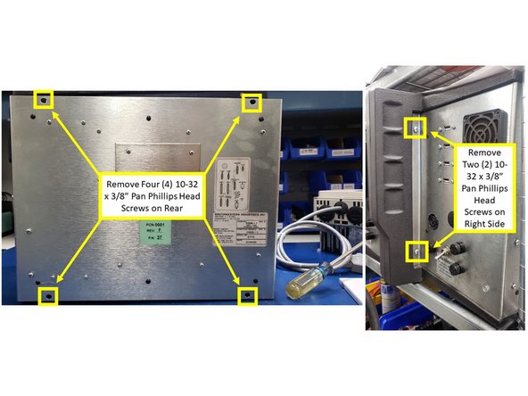
Remove four (4) 10-32 x 3/8" Pan Phillips Head Screws from the rear and two (2) from the right side of the SX Pendant that are securing the computer module to the LCD/enclosure.
-
-
-
Pull the computer module a few inches and stop.
-
Pulling the computer module too far will damage the ribbon cables.
-
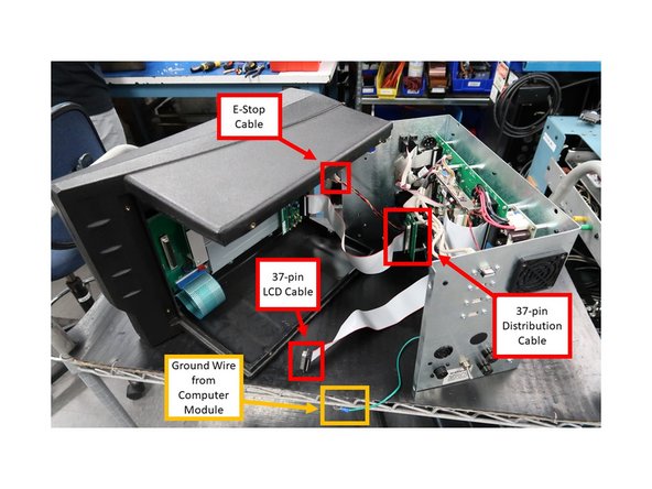
Reach from the top, and remove the 37-pin LCD cable, 37-pin distribution cable and the 9-pin E/Stop cables.
-
The above cables are to stay with the computer module.
-
Next, slide the module about 1/2 way out of the LCD/enclosure.
-
Remove the ground wire from the LCD/enclosure side.
-
Lastly, slide the unit completely out of the LCD/enclosure.
-
-
-
Replace computer module or LCD/enclosure.
-
Follow the instructions in reverse order when reinstalling the new computer module or LCD/enclosure.
-
Make sure that all connectors are properly seated before fastening the unit back in place.
-
-
-
If applicable, you can save configuration files on a floppy disk or external drive via Service Code 142 prior to replacing the computer module, and/or load configuration files from a floppy disk/external drive via Service Code 141 on a new computer module after it had been replaced.
-
Service Code 142 allows you to save your configuration file to a floppy disk or external drive. The configuration file consists of items such as calibration and backlash constants. This code is used when a computer module or hard drive needs to be replaced. This stores the configuration file from the hard drive to the floppy disk.
-
Insert USB/floppy drive on the SX control. On the Service Code 142 screen, select the appropriate drive to save the configuration files to (D Drive will be available for most USBs), and choose YES.
-
It is a good idea to do this code after the machine is initially setup, so these values can be saved and used in the future.
-
If the computer or hard drive fails, then you will not have the ability to save the configuration file, and the machine will need to be re-setup when the computer or hard drive is replaced. If Service Codes 141 and 142 do not apply, please follow Step 8 of this guide.
-
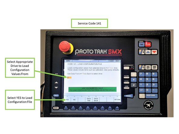
Service Code 141 allows you to load configuration files from the floppy disk or external drive to your hard drive. The configuration file consists of items such as calibration and backlash constants. This code is used when a computer module or hard drive has been replaced.
-
Insert USB/floppy drive on the SX control. On the Service Code 141 screen, select the appropriate drive to load the configuration files from (D Drive will be available for most USBs), and choose YES.
-
-
-
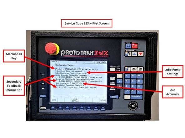
If running Service Codes 142 and/or 141 was successful on the new Computer Module, you can run Service Code 313 to display and confirm the current configuration files on your new computer module. Service Code 313 will feature two (2) screens:
-
Please note that the images provided on the left are used for reference information only; you would typically see values other than zero on both of the Service Code 313 screens.
-
The first screen of Service Code 313 displays the following information:
-
Machine ID Key, Lube Pump Settings (displays settings for Lube Cycle Time and Lube Discharge Time), Arc Accuracy (displays the measurement for Maximum Following Error on programs with sharp corners), and Secondary Feedback Information (Motor Encoder Calibration Constants, Secondary Feedback Calibration Constants, and enabling Secondary Feedback).
-
The second screen of Service Code 313 displays the following information:
-
Limit Switches (displays if limit switches are enabled for ram, saddle and table travel), if Spindle is enabled during Run Mode, Code 11 (measures how much motor motion is necessary to create table/saddle motion), Code 128 (displays backlash values for each axis), Code 12 (displays values and sets parameters for machine friction characteristics),
-
Accessory Key (displays the type of Auxiliary Function [Coolant, Air, Indexer] being used), and Code 100 (used to check the maximum feedrate of an axis and if the encoders are counting).
-
-
-
Per Step 6 above, If the computer or hard drive fails, then you will not have the ability to save the configuration file, and the machine will need to be re-setup when the computer or hard drive is replaced.
-
Machine must be calibrated using Service Code 123 and a calibration standard or other precision block.
-
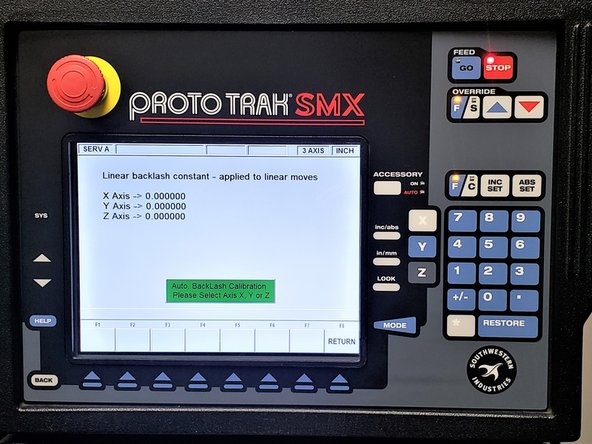
You must run Service Code 128 on your machine in order set up backlash values for each axis.
-
Please note that the recalibration process for the TRAK K3 SMX is going to be provided on an upcoming guide.
-
-
-
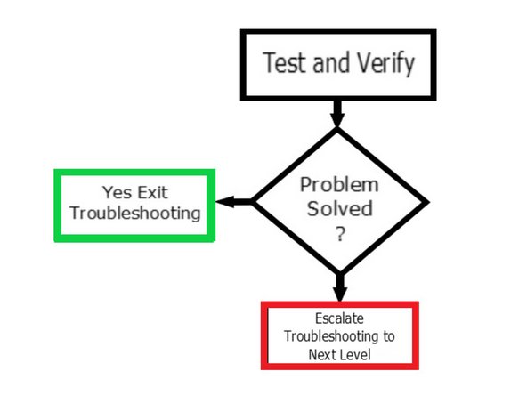
Test the axis and verify if the run away condition has been resolved.
-
If resolved, exit troubleshooting.
-
If not resolved, next step.
-
-
-
Power down the remove power cable to mill before changing the break out box.
-
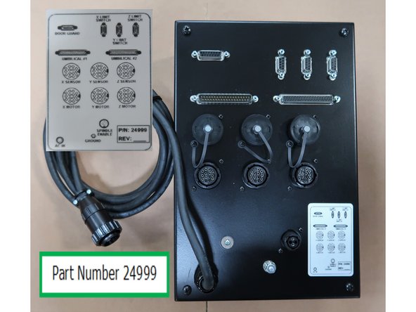
There are two version of the break out box based upon the mill. Verify you have the correct replacement breakout before disassembly of the mill.
-
Replacing the breakout box requires removal of the existing cables, unbolt the box from the mill and replacing it with the new box.
-
All of the cables need to be replaced as they were found on the old box. There is a label on the box cover showing the proper location of each cable on the box.
-
Part Number 24999 used on SX mills.
-
-
-
Test the axis and verify if the run away condition has been resolved.
-
Did the break out box replacement solve the issue? If yes, repair complete and exit troubleshooting.
-
If the problem still exists, diagnosis needs to be elevated to a higher level.
-