Introduction
Applies for TMC Models:
xxxEMxxxx (TMC5)
xxxENxxxx (TMC7)
xxxEPxxxx (TMC10)
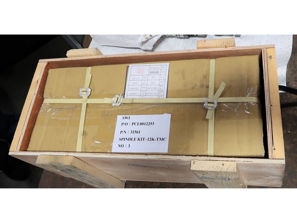
This guide is for TMCs manufactured approximately before November 1, 2021. These machines do not have the necessary spindle or space to mount the CTS components. This is a complex process to add both a new CTS capable spindle as well as the CTS components. The original 12K spindle option number is 31560.
-
-
Unscrew the 4 screws holding the tool holder clamp switch panel and slide it inside the spindle. The sheet metal surroundings need to be removed. Technician needed to adjust the height of the spindle for access to the left side and cut some zip ties for wire space.
-
Just loosen top bolts and leave them installed. Lower bolts are hard to access especially on the left side, so remove them first. You need to remove two plugs for the EHW option if so equipped. Careful of the wiring on the right side cover with EHWs. After the lower bolts are removed, remove upper bolts with panels. Panels can be heavy and awkward.
-
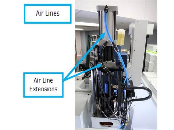
Turn off air supply from the rear panel. Disconnect air lines from the pneumatic cylinder. Remove the four nuts holding the cylinder platform and set it aside.
-
Note the orientation of the blue and black air lines at the top of the spindle. You may extend the existing air lines during this process. Make sure the blue line goes to the top of the air cylinder and the black hose goes to the bottom. You risk a mill crash if the hoses are reversed.
-
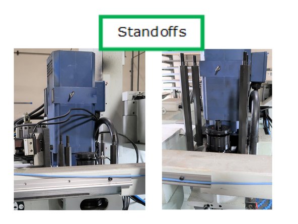
Remove tool detect sensor and wire. Remove the four stand offs.
-
-
-
Release the jam nut from the two belt tensioning screws. Remove both tensioners.
-
Loosen the 4 bolts that hold the motor mounting plate to allow for belt tension release. Remove the belt from the spindle motor sliding away as needed from the spindle for clearance.
-
-
-
E - Stop mill.
-
DO NOT AT ANY TIME ATTEMPT TO LIFT MOTOR BY HAND AS IT WEIGHS APPROXIMATELY 80lbs.
-
Use caution when moving the motor with cables attached. They could be a trip hazard or get damaged.
-
Two People for lifting over 50 lbs is recommended. Remove four screws holding motor. This is an 80 lb motor, two people needed to lay it on its side. Possible to use hoist but don't need to remove it from the mill for this upgrade.
-
-
-
DO NOT AT ANY TIME ATTEMPT TO LIFT MOTOR BY HAND AS IT WEIGHS APPROXIMATELY 80lbs.
-
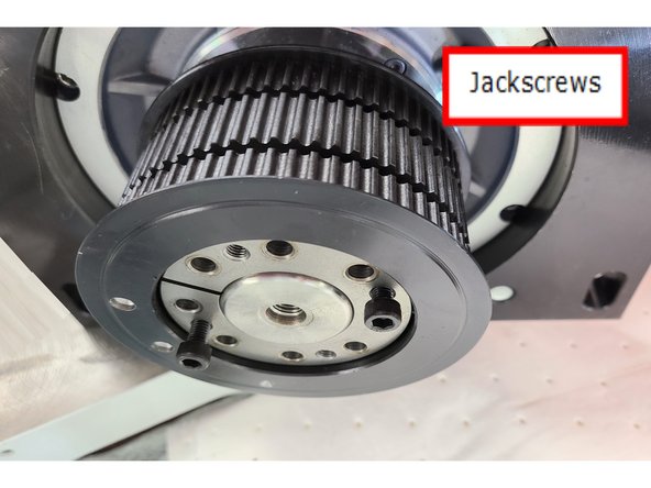
Photo shows 8 screws removed then 2 of 4 jackscrews installed preparing to slide out the tapered bushing. Remove the bushing and slide pulley away from the motor.
-
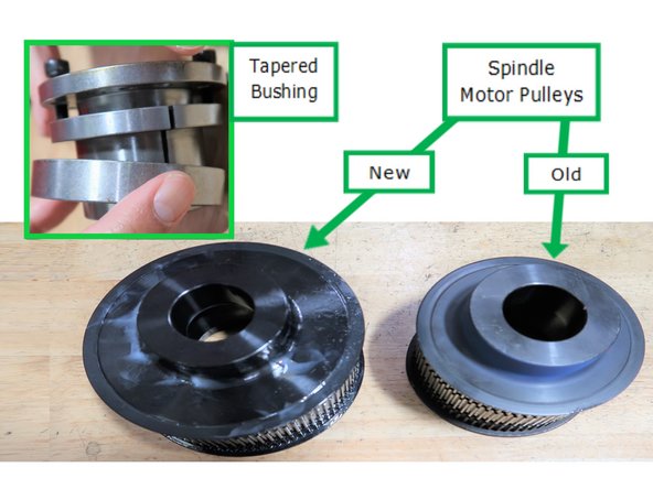
New pulley with tapered bushing shown (inset), also shows the larger size of the new pulley. Slide larger pulley onto the motor shaft. The tapered bushing holds onto the shaft and securing the pulley bore.
-
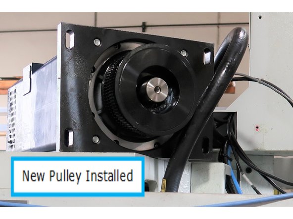
Photo shows new larger pulley installed.
-
Clean tapered bushing and push it and the pulley all the way against the shoulder on the motor shaft, as high up as it goes. Tighten the tapered bushing like a tire installation criss crossing the center to tighten another bolt on the opposite side. Go all the way around and then again to confirm they are all tight.
-
-
-
Clean the nose of the spindle to prepare for lowering into spindle replacement tool. Install spindle tool LOOSE to allow for slight position adjustment. Lower spindle until fully seated. Tighten table bolts on tool.
-
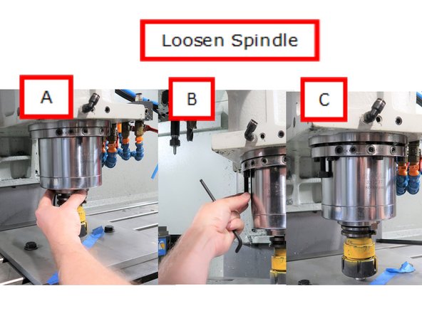
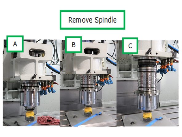
A - While lowering spindle carefully align spindle with tool for equal contact to the support tool. Zero the DRO for X & Y axes. B - Loosen spindle bolts, they stay in for support. C - Use jackscrew to start to force spindle out of casting. You want to keep the spindle touching the tool on the table while raising the casting just a little at a time
-
A - Jackscrews are removed while slowly raising the casting. B - Continue to raise casting slowly. C - Top of spindle pulley now showing.
-
Remove spindle from mill. use caution because the spindle is also heavy and oily (slippery).
-
-
-
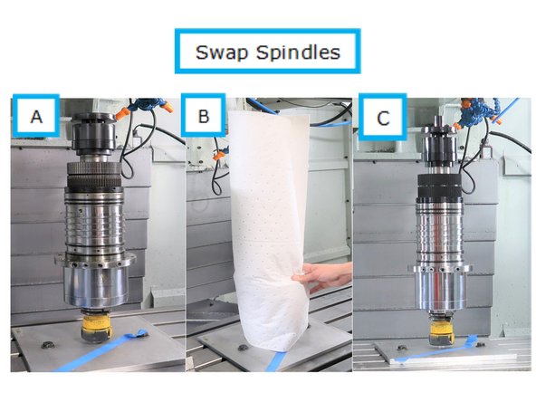
Carefully wrap new spindle to place it in position. Wrapping protects the side as well as the top plate.
-
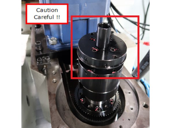
CAUTION - careful attention to the black shaft sticking out at the top of the new spindle. This is incredibly sensitive and cannot be dropped or hit against things during moving. Use care!
-
A - Original spindle. B - New spindle is carefully wrapped to protect outside surface as well as the top most metal plate. C - New Spindle.
-
Once new spindle is placed on tool holder, the wrapping can be removed.
-
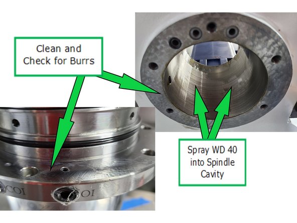
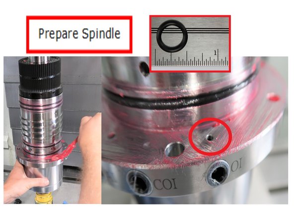
Spray WD 40 up into spindle cavity in casting. Wipe inside cavity after spraying to make sure fully cleaned (no dirt, debris, etc.). Then clean and check both upper and lower flanges for dirt and burrs.
-
-
-
Spindle O-rings are covered with lube. Special attention is given not to plug oil passageway. Don't get the lube close to oil passageway to allow for the lube to be compressed during installation. To protect that passage way after installation, a 1/2" o-ring is inserted into the flange above the hole on the casting (see insert).
-
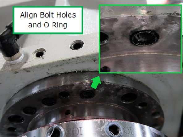
Lower the casting very slowly keeping in mind the holes in the spindle need to be aligned with the holes in the casting. Inset photo shows to align the 12K oil supply with the o-ring attached in the spindle groove on flange in casting and mated to the proper hole in the flange of the spindle. Twist the spindle as needed.
-
Stop the spindle flange close to the casting to test the alignment of the holes.
-
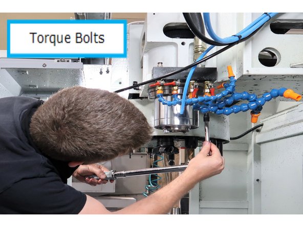
Use the cross pattern to install the spindle bolts. Use the stepped torque system every 10 lbs to a final torque of 30 lbs.
-
-
-
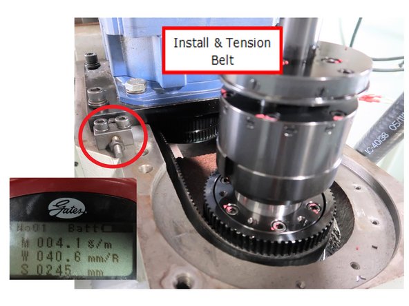
Install and tighten belt using Gates Sonic tension Meter 507C to 113 Hz by adjusting both tensioners. Tighten four M12 motor bolts to 50 ft/lbs.
-
Replace short standoffs with the longer ones, short end down into casting.
-
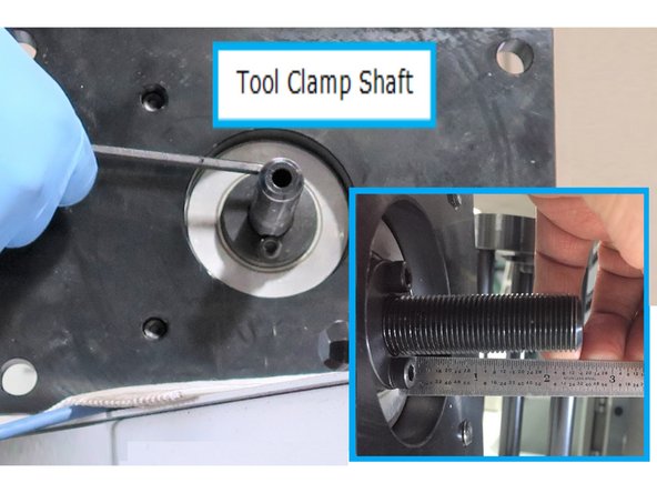
Install clamp shaft (with left hand threads) into tool clamp cylinder and base. Set the distance to the shaft by turning the shaft until 2 1/2" are exposed from the flange to the end of the shaft.
-
-
-
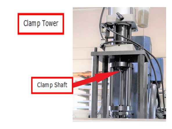
Place the clamp tower on top of the spindle add the tool clamp cylinder and base on top so the shaft fits through the clamp tower.
-
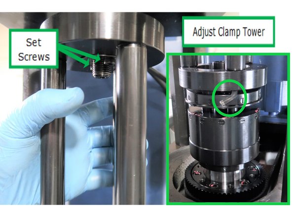
Adjust height of the clamp tower by placing 5 mm hex wrench under it and tighten the two set screws on top. Add nut with left hand threads to the clamp shaft loosely installed to the clamp tower. Adjust the height by screwing the tower up/down, and tighten. Replace 4 nuts and washers on the tool clamp cylinder.
-
Adjust clamp tower to have opening facing the right side of mill to allow connection for hose into rotary joint.
-
Use blue and black rubber tubing supplied with the kit to extend the length of the tubes to the spindle. Hoses are to be used with the couplers available in the Machine Assembly area. At some point, mills will come with longer hoses.
-
-
-
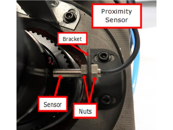
Assemble proximity sensor as shown. use two bolts to fasten bracket to casting in front of the spindle as shown. Gap between the spindle and edge of sensor should be 0.030". Rotate the spindle and make sure the light comes on and off. This will check the gap for proper operation of the sensor.
-
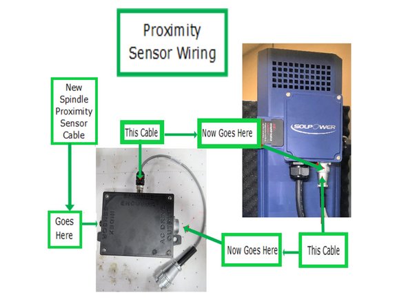
Install new front sensor and module, with wire changes as shown. Light weight module floats on the right side of spindle, mixed in the wires so does not need to be secured.
-
-
-
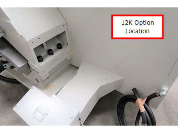
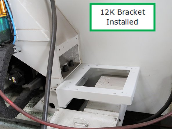
TMC left rear corner without the 12K Spindle Oil Cooler pump installed. Note that there are two sets of holes drilled and threaded in the casting for options to be installed.
-
Installed bracket in the proper location to support 12K pump.
-
Bracket is secured by 4 bolts included in the 12K kit.
-
-
-
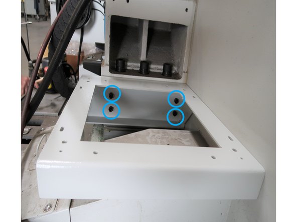
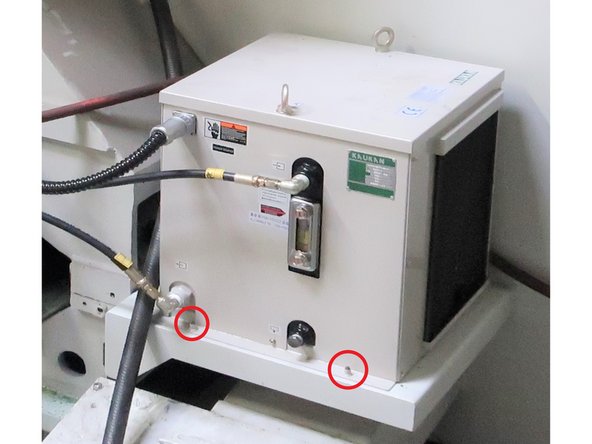
There are four bolts included in the kit that need to be installed from the bottom of the pump through the bracket into the pump housing for support. The two in the front are labeled with two others in the rear.
-
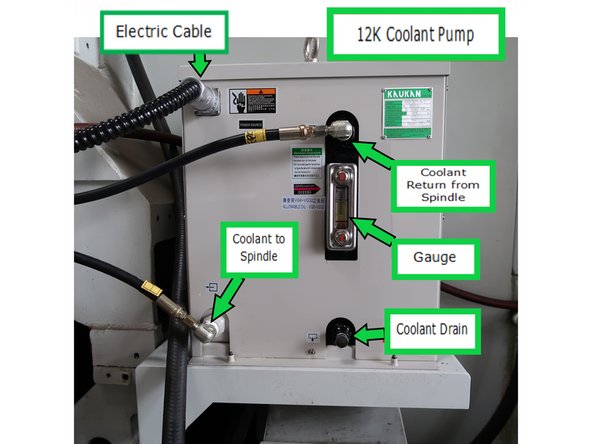
Pump connections are shown for the two hydraulic lines and the electric cable. Illustration shows the specific location for the outgoing and incoming coolant.
-
Always on when the mill is operational so no switching on and off.
-
-
-
While facing the back of the machine, remove the circular plate over the coolant tank that is located at the bottom left of the machine.
-
Install the Pump Riser over the circular hole by securing it with four bolts around each of its bottom corners.
-
Install the CTS Pump over the Pump Riser by securing it with four SHCS screws.
-
The CTS Pump with the Impeller weighs about 100 lbs. Have at least two people to lift the CTS Pump properly over the Pump Riser, or use a hoist.
-
-
-
The CTS option has two sensors (Filter Clog Sensor and Coolant Pressure Sensor) and a filter.
-
The Filter Clog Sensor is mounted to the filter body. The Coolant Pressure Sensor is installed on a pipe tee that is connected to the right side of the filter assembly. See first image on the left for the location of the two sensors and the filter.
-
The Filter Clog Sensor is designed to detect when the filter canister is clogged, and needs a replacement filter. The sensor detects a pressure differential between the fluid “In” pressure and the fluid “Out” pressure.
-
The standard PSI for the fluid "In" pressure varies based on the tool being used. If the pressure differential between “In” and “Out” is greater than 50 PSI, then the sensor displays a warning message on the pendant.
-
The Coolant Pressure Sensor checks for proper coolant pressure in the spindle. The Coolant Pressure Sensor is designed to stop the spindle if the pressure goes below the safety level. It monitors the coolant pressure in case of coolant runout or equipment failure. We’ll be setting this sensor later.
-
There is a warning message displayed on the pendant to give the operator a chance to correct the problem. If this warning message is triggered, the sensor halts the current program, and stops the spindle.
-
-
-
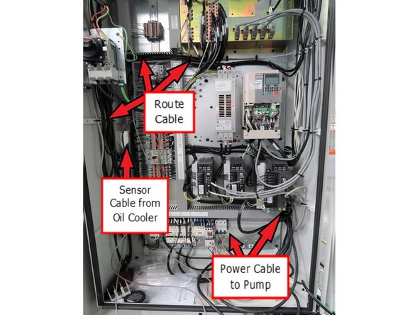
Cable routing shown for the power and sensor cables from the pump of the 12K oil cooler. Arrows show routing cables through wireways to protect them from interference due to power sources, etc.
-
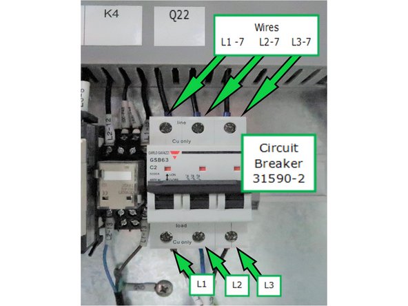
Install circuit breaker on the bottom rail in the cabinet as shown. Cable "Spindle Oil Cooler Pump" connects to the bottom of the Q22 circuit breaker. Wires on top of Q22 L1-7, L2-7 & L3-7 connect to corresponding terminal blocks TB 16-1, TB 18-1, TB 20-1.
-
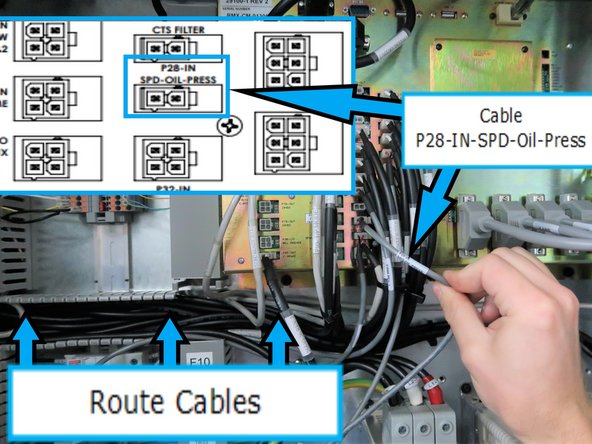
Route sensor cable from the opening at the left of the computer module, second row from the right and third connector from the bottom. Computer module is labeled with "P28-IN-SPD-Oil-Press". Route cable through wireways when possible.
-
-
-
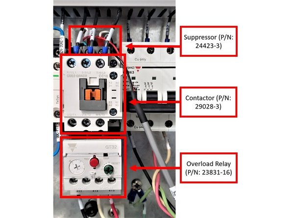
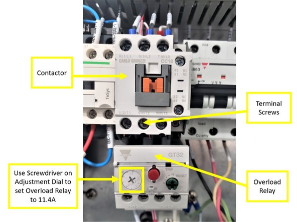
The CTS setup in the electrical cabinet will consist of the Contactor (P/N: 29028-3), the Suppressor (P/N: 24423-3), and the Overload Relay (P/N: 23821-16). Please see first image on the left for reference.
-
Suppressors are inserted in AC units to prevent damage to the equipment due to spikes in voltage.
-
Contactors are used for switching an electrical circuit on or off, and they provide a level of isolation away from high electrical currents, which protects workers and equipment.
-
Overload Relays are designed to protect AC circuits and motors against overloads, phase failure, long starting times, and prolonged stalling of the motor.
-
Install the Overload Relay to the Contactor as shown on the second image on the left. Once the Contactor is properly set up with the Overload Relay, make sure that the terminal screws on the Contactor are securely tightened.
-
Use a screwdriver on the adjustment dial to set the Overload Relay to 11.4A (see second image on the left).
-
Install the Suppressor on top of the Contactor, as shown on the first image on the left. Leave the Suppressor Pigtails alone for now.
-
Once the Contactor, the Suppressor, and the Overload Relay are assembled together, install the back of the Contactor to the right side of the bottom DIN rail (under K22) in the electrical cabinet.
-
-
-
Install the P36-OUT CTS Cable Assy (P/N: 31591 Rev B) and the CTS Overload Wire Assy (P/N: 31591-1) between the Contactor, the Overload Relay, and the P36-OUT port on the computer module:
-
Make sure that you are using Rev B or higher of the above P36-OUT CTS Cable in order to prevent any wiring issues!
-
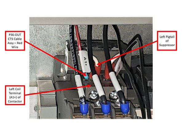
Connect the Left Pigtail of the Suppressor and the Red Wire of the P36-OUT CTS Cable together on the left coil terminal (A1+) of the Contactor.
-
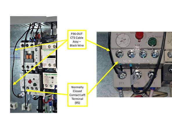
Connect the Black Wire of the P36-OUT CTS Cable to the Normally Closed Contact Left Terminal (95) of the Overload Relay.
-
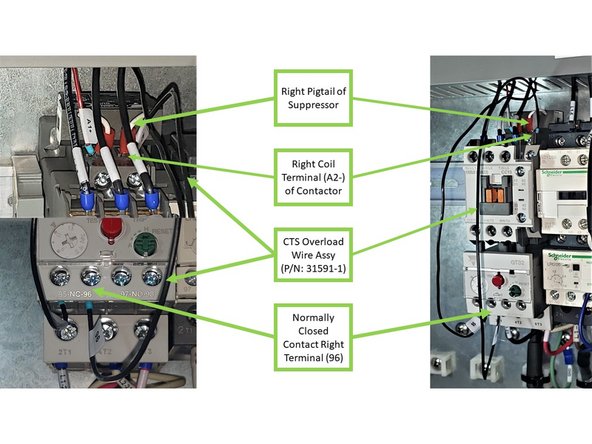
Connect one end of the CTS Overload Wire Assy to the Normally Closed Contact Right Terminal (96) of the Overload Relay, and connect its opposite end together with the Right Pigtail of the Suppressor on the right coil terminal (A2-) of the Contactor.
-
Once the Suppressor Pigtails, the Red and Black Wires of the P36-OUT CTS Cable, and the Overload Wire Assy are correctly installed to both the Contactor and the Overload Relay, make sure that all applicable terminal screws are tightly secured.
-
-
-
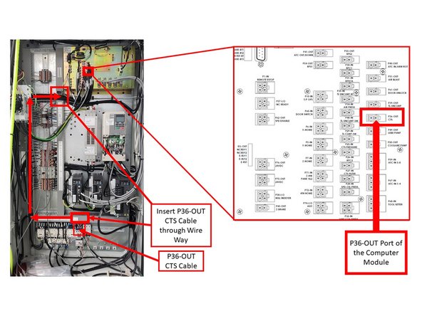
Insert the P36-OUT CTS Cable Assy through the Electrical Cabinet Wire Way (as shown on the second image on the left), and install the opposite end to the P36-OUT port of the computer module.
-
Please refer to Part Number 29100-1 for the location of the P36-OUT port on the computer module; it is included at the bottom of this guide.
-
Install each wire of the Wire Assy Kit (P/N: 31597) to their designated areas on the main terminals of the Contactor: install the L1-5 wire to the R/1/L1 terminal; the L2-5 wire to the S/3/L2 terminal; and the L3-5 wire to the T/5/L3 terminal.
-
Insert the opposite ends of each wire of the Wire Assy Kit through the wire way, and install them on their designated terminals on the adjacent Contactor to left (labeled as K11): install the L1-5 wire to the 1L1 terminal; the L2-5 wire to the 3L2 terminal; and the L3-5 wire to the 5L3 terminal (see image).
-
Once the Wire Assy Kit had been properly installed on both contactors, make sure that the terminal screws on both contactors are tightly secured as well.
-
-
-
Oil cooler assembly control cable consists of pump power cable and sensor feedback cable. Both cables are in the same housing when connected to the oil cooler pump. The housing runs across the rear of the spindle where they separate.
-
The sensor feedback cable enters the electric cabinet from behind on the inner corner mount with the chassis along with other signal cables. The power cable enters the electric cabinet from behind the outer side along with other power cables.
-
-
-
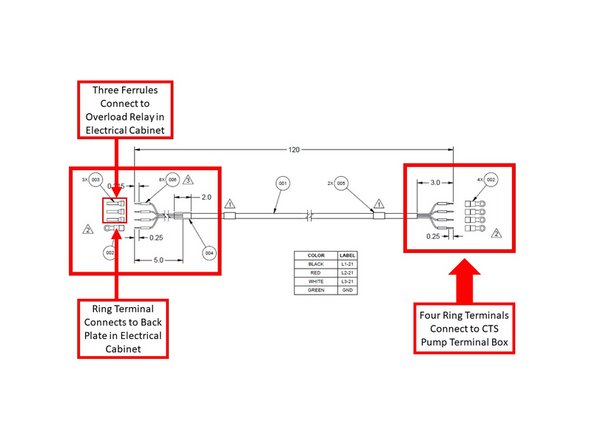
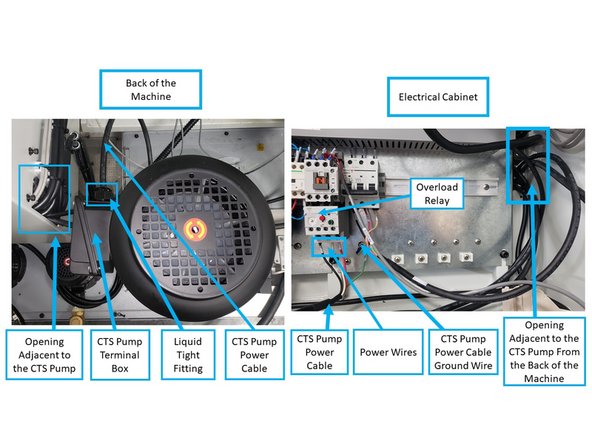
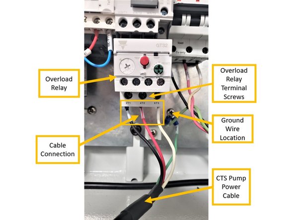
Install the CTS Pump Power Cable (Part Number 31592) from the CTS pump terminal box to the Q21 Overload Relay, and is ground wire to the GS36 location in the electrical cabinet. See first image on the left for a diagram of the CTS Pump Power Cable.
-
Insert the end of the CTS Pump Power Cable that has four ring terminals (see first image on the left) to the CTS Pump Terminal Box through the new liquid tight fitting (Part Number 31696). Install the combined liquid tight fitting and CTS Pump Power Cable on the terminal box itself.
-
On the opposite end of the CTS Power Cable, connect the power wires to their corresponding terminal screws and ground to chassis on the electrical cabinet (see first image on the left).
-
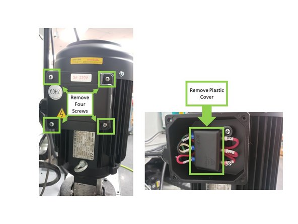
Open the terminal box by removing the four screws around each corner of the terminal box cover. Once removed, also remove the plastic cover that covers the wiring inside the terminal box.
-
-
-
There will be pink wires coming from within the terminal box with the following labels: U1, U2, V1, V2, W1, and W2, along with label instructions for both high and low voltage installation. Per the first image on the left, follow the instructions for low voltage installation:
-
Top row: combine the black wire (L1-21) with the pink U1 wire on the left, and set the pink W2 wire on the right. Second row: combine the red wire (L2-21) with the pink V1 wire on the left, and set the pink U2 wire on the right. Bottom row: combine the white wire (L3-21) and the pink W1 wire on the left, and set the pink V2 wire on the right.
-
While facing the back of the machine, insert the opposite end of the CTS Pump Power Cable through the opening adjacent to the CTS Pump, and into the electrical cabinet (see third image on the left).
-
Install the CTS Pump Power Cable in the following manner (see image on the left):
-
Install the black wire (L1-21) to the "2T1" slot on the Overload Relay; red wire (L2-21) to the "4T2" slot, and the white wire (L3-21) to the "6T3" slot.
-
Install the ring terminal (ground wire) to its designated location on the electrical cabinet.
-
-
-
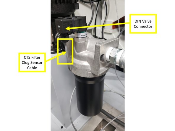
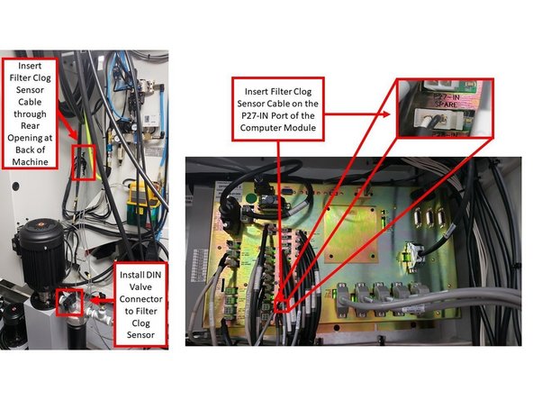
The following process details how to connect the CTS Filter Clog Sensor Cable to the computer module inside the electrical cabinet.
-
The Part Number for the CTS Filter Clog Sensor Cable is P/N 31593.
-
Install the end of the CTS Filter Clog Sensor Cable that contains the DIN Valve Connector to the sensor itself. Secure the DIN Valve Connector to the sensor with a Philips screw.
-
The opposite end of the CTS Filter Clog Sensor Cable enters the cabinet from behind on the inner corner mount with chassis along with other signal cables. Connect it to the port labeled as "P27-IN" on the computer module inside the electrical cabinet.
-
Please see third image on the left for the location of the P27-IN port on the computer module; it is also included on the Part Number 29100-1 document that is attached at the bottom of this guide.
-
-
-
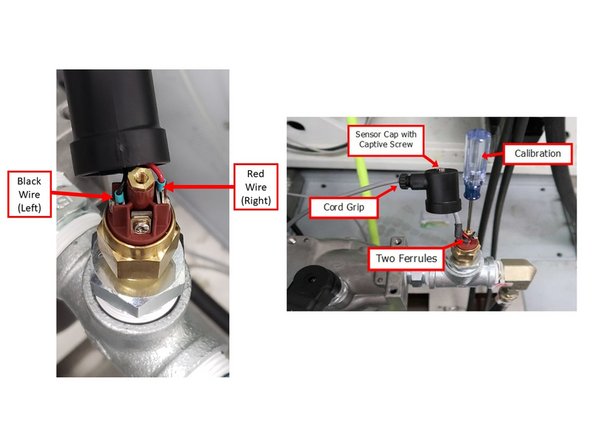
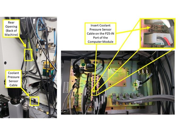
The following process details how to connect the CTS Coolant Pressure Sensor Cable to the computer module inside the electrical cabinet.
-
The Part Number for the CTS Coolant Pressure Sensor Cable is P/N 31594.
-
Connect the end of the Coolant Pressure Sensor Cable that contains the red and black wires to the sensor itself. Install the red wire on the right connector, and the black wire on the left connector.
-
Using a screwdriver, secure the captive screw over the sensor cap at the top of the sensor. Do not tighten the cord grip yet, because the Coolant Pressure Sensor still needs to be calibrated at a later step.
-
The opposite end of the Coolant Pressure Sensor Cable enters the cabinet from behind on the inner corner mount with chassis along with other signal cables. Connect it to the port labeled as "P25-IN" on the computer module inside the electrical cabinet.
-
Please refer to Part Number 29100-1 for the location of the P25-IN port on the computer module; it is included at the bottom of this guide.
-
-
-
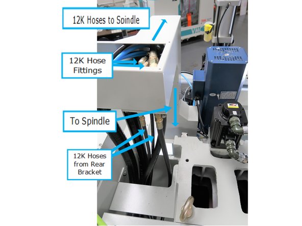
Hoses have to traverse a long path going through the flexible loop on the spindle. Hoses start from the pump and are connected to fittings along the back of the first bracket.
-
First bracket requires fittings for both coolant hoses.
-
Long hoses take a loop here to compensate for the spindle travel. Bracket in the center to manage the fluid hoses needs to be removed and have fittings added. This step routes the cables into the spindle.
-
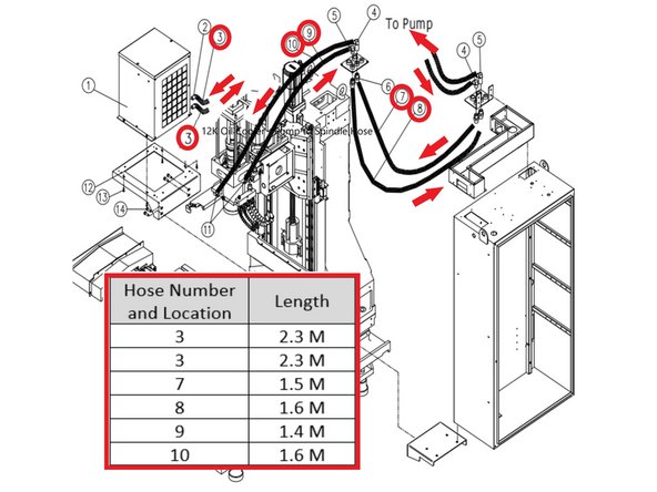
Next step shows the correct hose and length for each location.
-
-
-
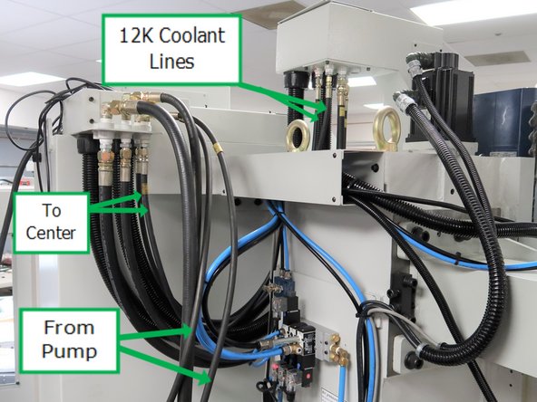
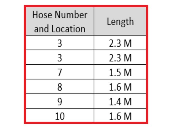
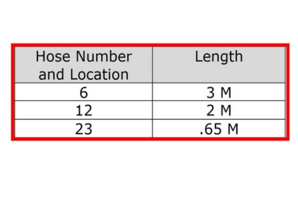
Photo is labeled as to the location of each 12K coolant hose. The chart gives the correct length for each location.
-
-
-
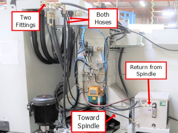
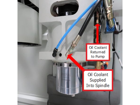
Hose connections shown for the supply of coolant from the pump as well as a connection to returned heated coolant back to pump.
-
-
-
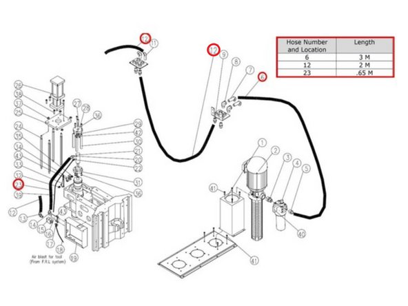
Photo is labeled as to the location of each CTS coolant line hose. The chart gives the correct length for each location.
-
The following are the Part Numbers for the CTS coolant hoses:
-
3 M CTS Hose Coolant (P/N: 31572)
-
2 M CTS Hose Coolant (P/N: 31574)
-
.65 M CTS Hose Coolant (P/N: 31578)
-
-
-
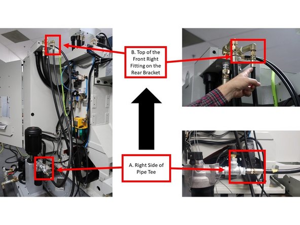
While facing the back of the machine, route coolant lines by installing a 3 m hydraulic hose on the right side of the pipe tee that also houses the Coolant Pressure Sensor (labeled as "A" on the first left image), and installing the other end to the top of the front right fitting on the rear bracket (labeled as "B" on the first left image).
-
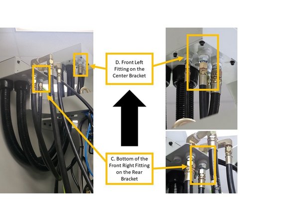
From the rear bracket, continue the coolant line by installing a 1.6 m hydraulic hose at the bottom of the front right fitting (labeled as "C" on the second left image), and installing the other end to the front left fitting on the center bracket (labeled as "D" on the second left image).
-
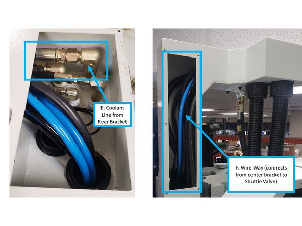
From the front right fitting within the center bracket (see top view of center bracket that is labeled as "E" on the third image on the left), direct the coolant line by installing a 2 m hydraulic hose through to the wire way (labeled as "F" on the third image on the left).
-
-
-
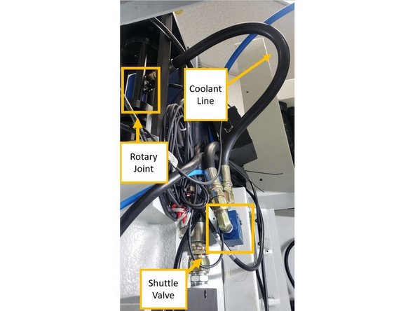
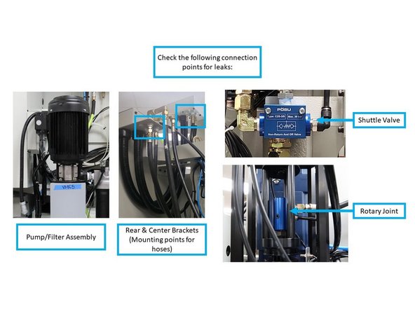
While facing the front of the machine, install the Shuttle Valve and its bracket on the right side of the sheet metal above the spindle.
-
Install the bracket on the sheet metal with two bolts, and then install the Shuttle Valve itself onto the bracket with two bolts. Some machines may need the sheetmetal box drilled and tapped. Future machines will come with holes pre-drilled.
-
The Shuttle Valve has three points of connection:
-
Install a 90° elbow (gold) on the left side of the Shuttle Valve in order to connect it to the coolant line that is coming from the center bracket through the wire way.
-
On the top of the Shuttle Valve, install a silver fitting that will continue the coolant line from the Shuttle Valve to the Rotary Joint.
-
On the right side of the Shuttle Valve, install a 90° Push to Connect fitting in order to connect the Shuttle Valve to the air cylinder above the spindle.
-
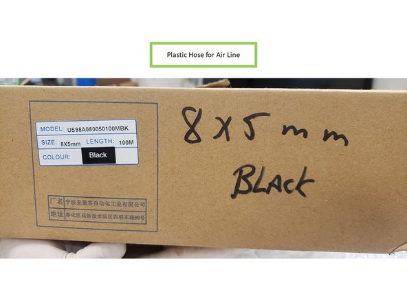
Please note that the plastic hose connecting the Shuttle Valve to the air cylinder will need to be replaced by a longer hose; the hose that comes with the kit may be too small. An available spool of the plastic hose is located in the Big Room above the parts cabinet; cut to length for the appropriate size.
-
-
-
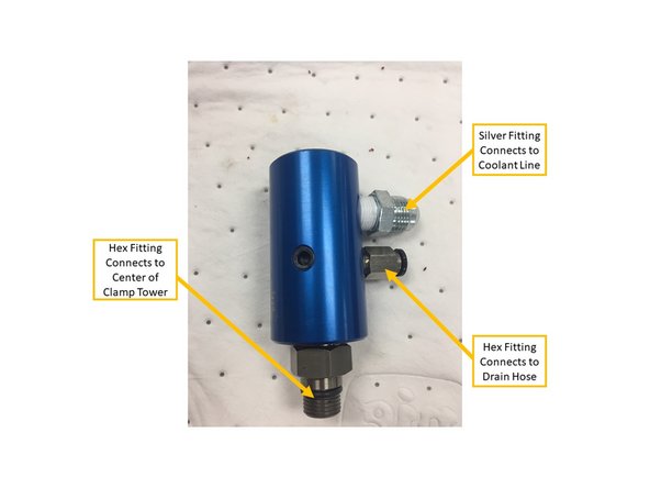
The Rotary Joint connects the coolant line to the top of the spindle, which allows coolant to flow down through the spindle and into the cutting tool.
-
Prepare the Rotary Joint by installing the correct fittings on it as shown on the first image on the left. Per the image, the top silver fitting connects to the coolant line, the hex fitting directly below connects to the drain hose, and the hex fitting at the very bottom connects to the center of the clamp tower on top of the piston.
-
Install the Rotary Joint at the center of the clamp tower above the piston on top of the spindle. Tighten snugly by hand to approximately 25ft-lbs. Use an adjustable wrench on spindle dogs to hold spindle from rotating.
-
The Rotary Joint is a left-handed thread.
-
Insert the coolant line by installing a 0.65 hydraulic hose on the silver hydraulic fitting on the Rotary Joint itself.
-
On the hex fitting below the coolant line, attach the drain hose to the Rotary Joint, and route its opposite end to the sheetmetal box on the right side of the casting.
-
-
-
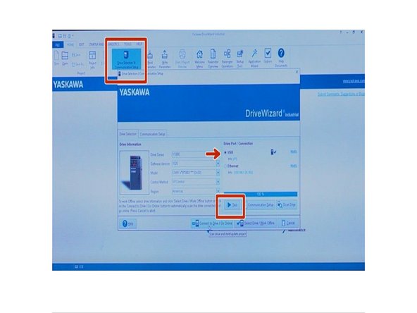
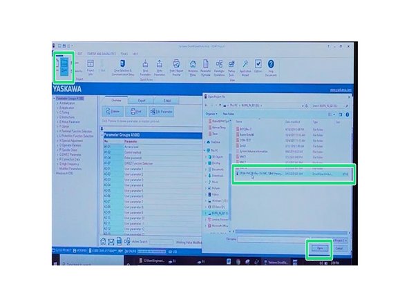
This step will give instructions on how to program the AC Drive. File name stored in the laptop has the format 29166-TMC-12K AC Drive. File names correspond to the mill; TMC 5/7/10/12/14. with the 12K option. You will need a USB 2.0 Type A and B and a laptop with the Drive Wizard Industrial Software. .
-
Prior to programming verify there are no errors displayed from the AC Drive. Use a standard USB 2.0 Type A and B to program. Next, connect B side to AC Drive USB port and A side to laptop.On the laptop launch the 'Drive Wizard Industrial software.
-
In the software open Drive selection & Communication Setup icon. Notice it will generate a window, on that window verify that it reads USB connection. Next press TEST it will start loading the appropriate parameters for the AC Drive.
-
The revision for the AC Drive parameter program file may change. Check with your Lead and/or Supervisor for the latest revision.
-
Click on View Edit Drive Parameters Click Open icon, select 29166-TMC 8K Rev 18 file, click No, Click OK.
-
-
-
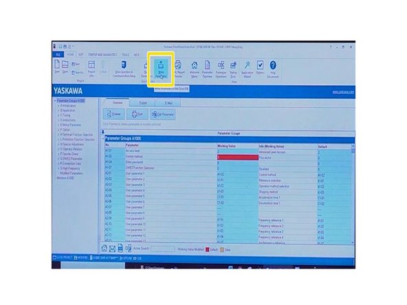
Click on Write Parameter icon, click Close, Click Yes. (Software will download parameters to AC Drive) AC Drive has been successfully programmed.
-
-
-
Update the ProtoTRAK software to Version 2.4.0 or later.
-
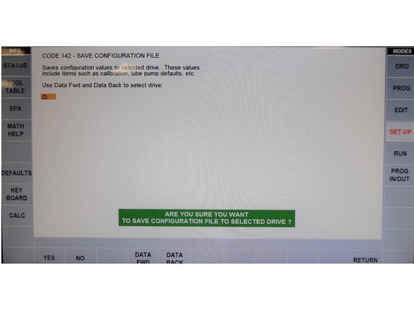
Run Service Code 142 to save the machine's configuration to USB flash drive. You will get a message to confirm to save the file to the USB.
-
Follow the steps in the attached document, "Instructions for Upgrading TMC Config Files" to edit and rename the configuration on USB flash drive. The attached document is provided at the end of this guide.
-
Replace the Machine ID Key with the 12K version of the machine's current model. Cycle power after replacing the Machine ID Key.
-
Confirm the spindle runs in forward and reverse.
-
Warm up spindle for 5 minutes at 1,000 RPM. Measure Spindle RPM’s with tachometer, and confirm on screen that they match at 3K, 6K, 9K and 12K.
-
-
-
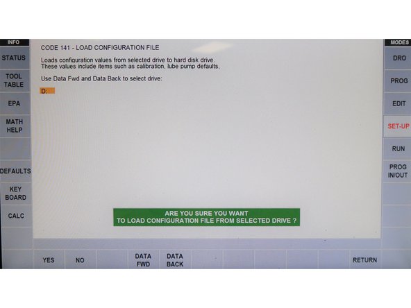
Run Service Code 141 to load the new configuration back into the machine. You will see a message confirming your interest to load a file from the USB. After the file uploads into the mill, you will be asked to cycle power.
-
-
-
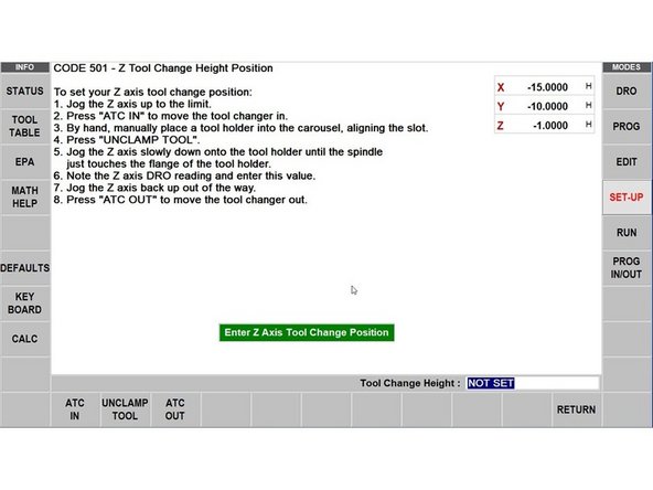
An automatic tool change requires that many components of the TMC work in concert with one another. With the spindle change, it is important this is done.
-
These components include the ATC (Position relative to the centerline of the spindle), the spindle (Orientation of the spindle drive dogs relative to angle of the tool holder held in the ATC), the Z-axis (tool change height) and the Automatic Draw Bar (being in state of clamped or unclamped).
-
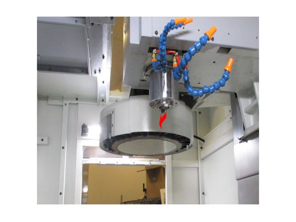
The arrow shows the dogs lined up with the center of the ATC where it can change tools when changer is aligned.
-
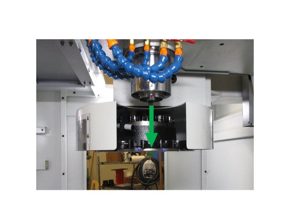
The arrow is the spindle aligned with ATC ready for a tool into tool slot #1.
-
Let’s start with spindle orientation. Spindle orientation is like any other setting regarding the ATC, it is a critical one, as a crash would be the result of an improper setting. Spindle orientation centers the drive dogs of the spindle for proper engagement of the CAT40 tool holder when it is held in the tool carousel of the ATC.
-
-
-
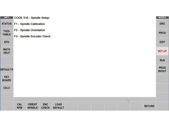
Go into SETUP on the pendant, select SERV CODES from the bottom row menu and then enter "510" at the prompt.
-
Select F2 Spindle orientation from the main menu. The second screen will give you step by step details in order to make sure the spindle and the system software are properly synchronized.
-
-
-
Follow the instructions on the screen carefully. Purpose of this is to double check the tool change height.
-
-
-
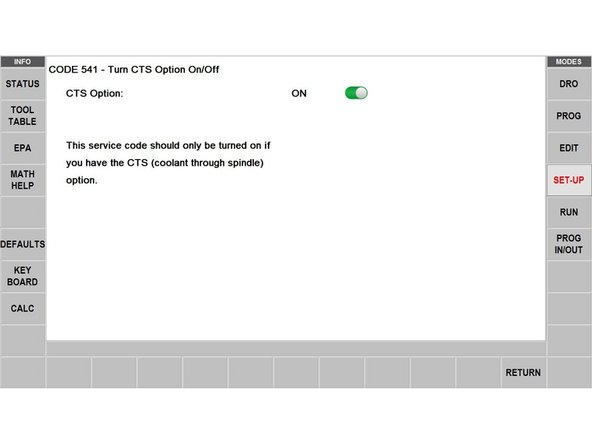
Service Code 541 allows users to turn the CTS Option on and off.
-
Service Code 541 should only be turned on for machines actually have the CTS option! Otherwise, do not turn on this Service Code because it will cause issues with the machine.
-
Service Code 541 can be readily accessed on new machines. It can also be accessed with machines that have the updated software Version 2.4.0 or later.
-
Turning on Service Code 541 enables the monitoring capabilities of the Filter Clog Sensor and Coolant Pressure Sensor (as mentioned in Step 14 of this guide). It also enables the use of the CTS On/Off hard key button on the pendant.
-
-
-
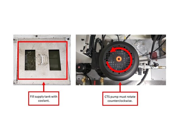
Fill the supply tank with coolant and turn on CTS at the pendant. Make sure that the CTS pump is rotating in the correct direction (counterclockwise). There is an arrow on the motor to check this.
-
Coolant coming out of the spindle is not an indication that the pump is turning in the proper direction. Observe the direction of the motor fan.
-
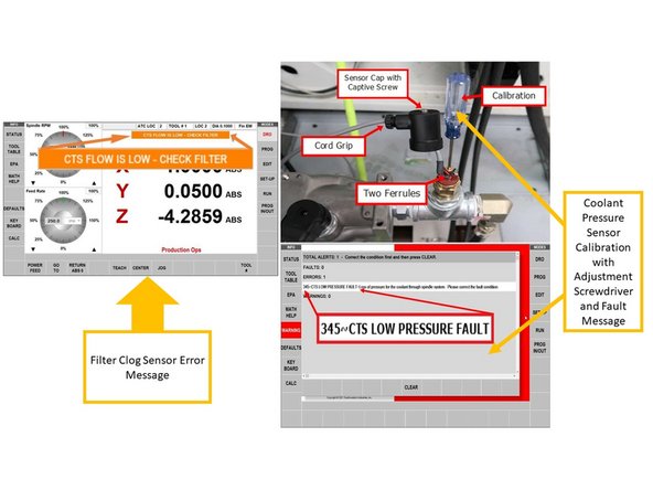
Test filter clog sensor. Turn the pump on, and unplug inputs to see the "CTS FLOW IS LOW" message flash on screen (left image). Replace inputs.
-
Calibrate the coolant pressure sensor through the following steps:
-
If the spindle has a tool in it, remove it prior to calibration.
-
Note the adjustment screwdriver for calibration (upper right image). Using a screwdriver slowly tighten the screw on the top center of the sensor approximately 1/8th of a turn per second.
-
When the machine faults out (lower right image), loosen the screw ¼ turn, and clear the fault on the pendant.
-
Run the CTS pump for 10 minutes, and check the following connection points below for leaks: pump/filter assembly, both mounting points for hoses (center and rear brackets), shuttle valve, and rotary joint on spindle. The spindle does not need to be turned on during this process.
-
-
-
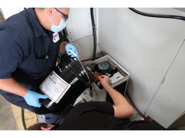
TRAK recommended oil: Quality ISO 32 oil, Anti-Wear additive. Pump capacity 4 liters which may need to be topped off once lines and spindle passageway is filled.
-
Fill spindle coolant pump with fluid. Run the pump to prime the system. The system holds more than the filling tank in the pump enclosure. This is a good time while the filling tank is not full to verify system operation. The return hose connects to a metal pipe that goes down into the filling tank.
-
When the level is low, you should be able to see bubbles in the fluid coming through the system. Now look over the whole system for leaks. This includes the fittings on the bracket at the rear of the mill as well as the junction plate at the top of the spindle. All of the hoses and fittings should be checked for leaks. Run test 10 - 15 minutes.
-
Fill the tank to about the top of the gauge while the pump is working.
-
-
-
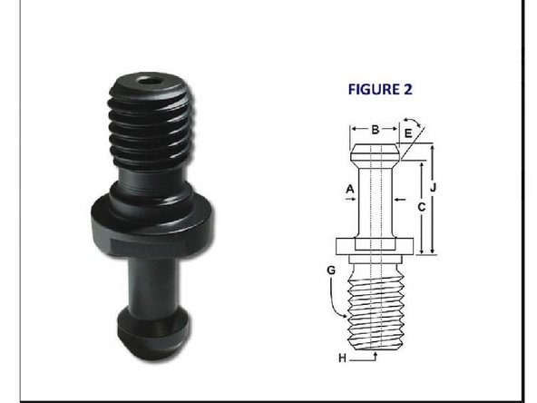
Our CTS option can be used with collet-mounted tooling or with drilled tooling, once a CTS compatible retention knob is installed in the tool holder.
-
The TMC5/7/10 uses CAT40 retention knobs. If the CTS option is purchased for the TMC5/7/10, you will need retention knobs similar to TMC5/7/10, but with holes.
-
Retention knobs for the CTS Option can be purchased through TRAK Machine Tools under part number: RETN KNOB KIT-CTS.
-
-
-
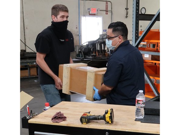
Caution heavy item: use two people as needed to pack spindle for return shipping.
-
The 8K spindle that has been removed from the mill for this upgrade is a valuable resource and needs to be well oiled, wrapped, boxed and crated reusing the original new spindle packing materials.
-
TRAK gets over $2,000 credit for the return of unused spindles which will go back to production and be installed in another mill. Contact shipping for proper handling and paperwork.
-