-
-
To align the ATC Carousel to the spindle on the TMC you need to know there are 3 adjustment points. Point number 1, number 5, and number 6 as shown on the drawing. Number 5 is used to adjust the carousel in the Y axis and 1 and 6 adjust in the X axis.
-
The ATC comes aligned from the factory so using alignment points 5 and 6 shouldn't be needed unless there has been a major crash or the ATC assembly or carousel has been removed, replaced or is grossly out of alignment.
-
Please Note: if you do need to adjust the ATC in the Y axis, the bracket that mounts the ATC assembly to the column is pinned to the column with taper pins that will need to be removed to align in the Y axis. Once the bracket has been adjusted in the Y you will need to drill and taper ream new holes to re-pin the bracket to the column.
-
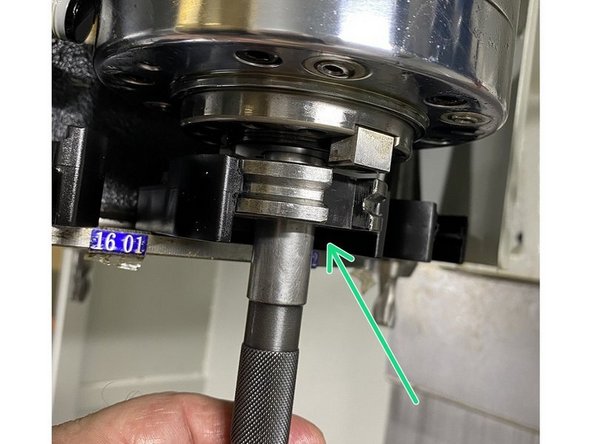
One more thing that should be noted is that when aligning the carousel to the spindle, the spindle has one black drive dog, this drive dog should be pointing towards the carousel when the spindle is correctly oriented to make a tool change.
-
-
-
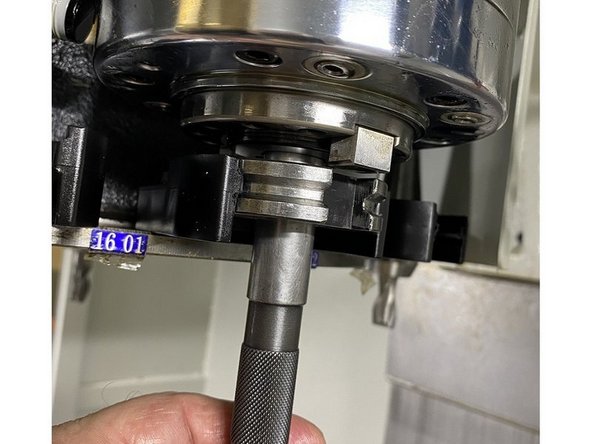
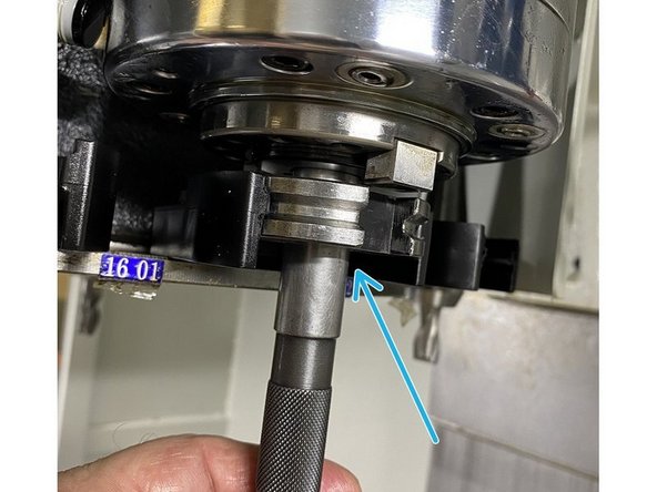
In order to verify the alignment of the ATC you will need the ATC alignment tool set. It consists of a taper tool, an alignment ring tool and a gauge pin. The taper tool is installed in the spindle, the ring tool is installed into one of the tool grippers in the carousel and the gauge pin is used to verify alignment in tool change position.
-
Install the taper alignment tool by raising the Z axis to its maximum height, then unclamping the spindle and inserting the taper tool into the spindle, and then clamp the spindle onto the tool.
-
Keep spindle at its max height and enter service code 501, press "ATC in" to move carousel under spindle. With the carousel under the spindle insert the ring tool onto the gauge pin and use the pin to assist in pushing the ring tool into the tool holder in the carousel. Make sure the witness mark in the ring tool is facing into the gripper.
-
Note: the slots for the drive dogs in the CAT 40 ring tool are not symmetrical, if the ring tool is inserted with the witness mark facing away from the gripper, the spindle to carousel alignment will be off.
-
-
-
Ensure the carousel is under the spindle and the taper and ring tools are installed, and slowly lower the spindle until it is just above the ring tool. Insert the gauge pin into the ring tool , if the ATC is properly aligned the gauge pin should slide easily through the ring tool and into the taper tool with little to no resistance.
-
If you do find the ATC is out of alignment check a couple of places on the carousel, a damaged gripper could also make it appear that the ATC is out of alignment. If you do find that only one location is out of alignment replace the gripper in that location and check it again.
-
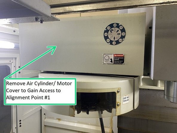
If the ATC needs to be aligned you will need to remove the ATC cover to get to alignment points one (1) and six (6).
-
To determine which way the carousel needs to be moved slowly raise the spindle above the ring tool about 2 inches, insert the gauge pin into the ring tool and look at where the gauge pin hits the taper tool. You should be able to tell if the carousel needs to move in the X, Y or both directions.
-
If it appears that the ATC only needs to be adjusted in the X Axis, and only a small amount skip to step 7. Step 7 is for minor X Axis adjustments only.
-
-
-
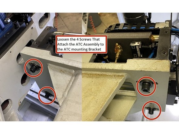
To align the ATC carousel in the X Axis loosen the four (4) M16 screws that attach it to the ATC mounting bracket. Loosen them but leave them snug.
-
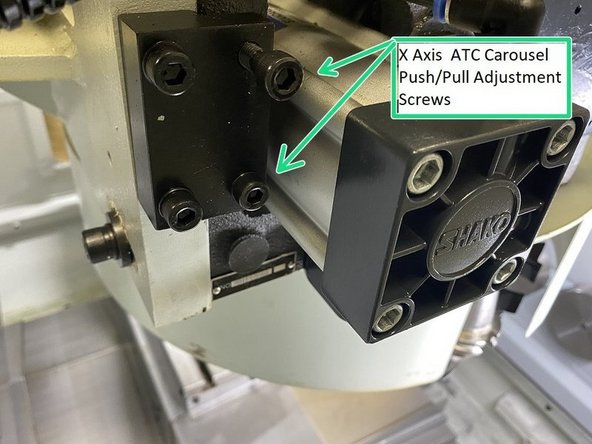
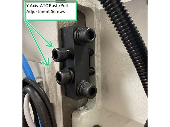
To move the carousel in the X Axis adjust the Push/Pull adjustment screws by loosening the push and tightening the pull or vice versa depending on which way the carousel needs to move.
-
Adjust the carousel until the gauge pin slips into the ring and taper tools with little to no resistance.
-
You may need to go back and forth a few times to get the carousel into alignment. You may also need to adjust in the Y Axis as well as the X in order to get the ATC into proper alignment.
-
-
-
If the ATC needs to be aligned in the Y Axis, then you will need to use alignment point #5. It is possible if the ATC has been crashed or the ATC assembly has been removed or replaced you may need to adjust in both the X and Y directions.
-
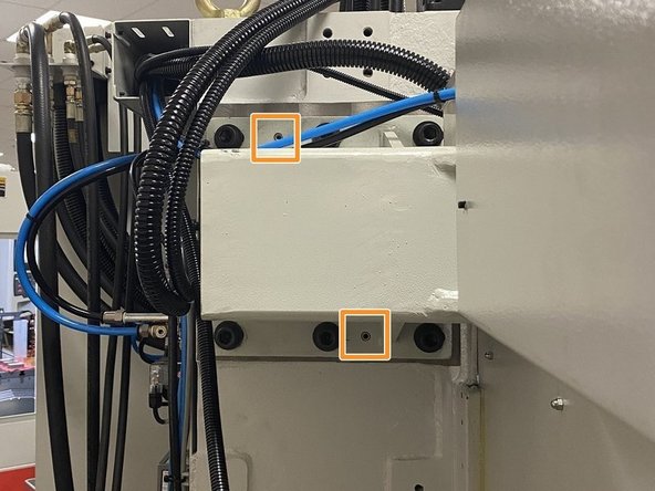
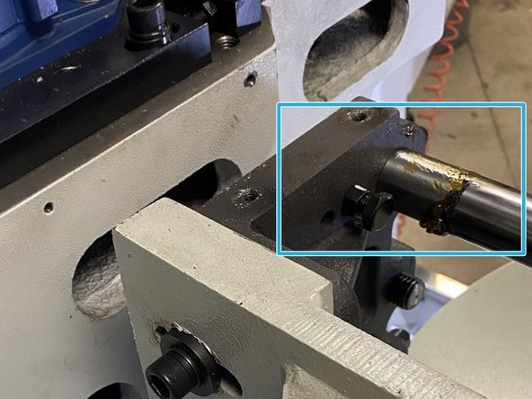
There are two (2) pins used to hold the position of the ATC bracket to the column, they will need to be removed before the carousel can be adjusted in the Y Axis.
-
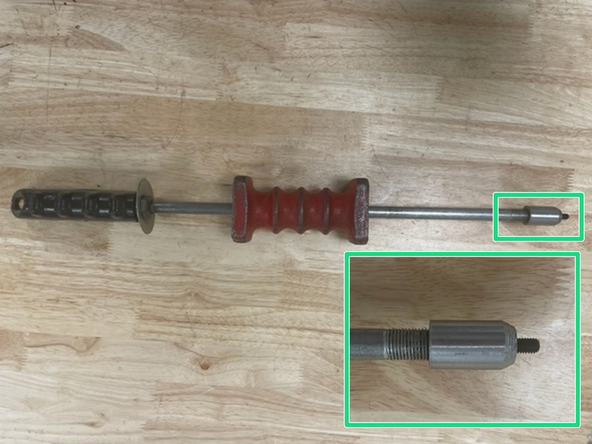
Set up a Slide Hammer with an M6 Bolt that will be used for removing the pins holding the ATC bracket and assembly.
-
Thread the M6 Bolt on the Slide Hammer into the pins on the ATC bracket and the ATC assembly, then slide the handle, with force, away from the pins to remove them.
-
Keep the two (2) pins for use when ATC alignment is done. New holes will need to be drilled and taper reamed when ATC alignment is completed.
-
-
-
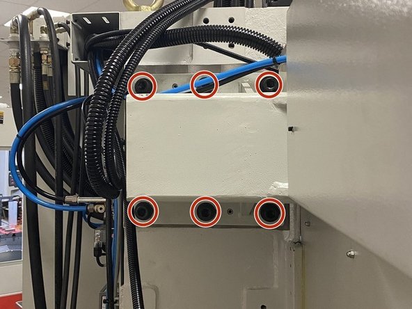
To adjust the ATC in the Y Axis you will need to loosen the six (6) screws securing the ATC adapter to the column casting. Loosen the mounting screws but keep them snug.
-
Install the taper and ring tools of the 3 piece alignment tool set into the spindle and carousel. Adjust the carousel in the Y axis by adjusting either the push or pull screw for the Y Axis until the gauge pin slips into both the ring and taper tools with little to no resistance.
-
You may need to go back and forth between the X and Y adjustments a few times to get the ATC into alignment.
-
Once the ATC has been aligned torque the six (6) M16 mounting screws to 100 ft-lbs and redrill and taper ream the ATC mounting bracket and reinstall the 2 pins. Reinstall the covers ATC Alignment is complete.
-
-
-
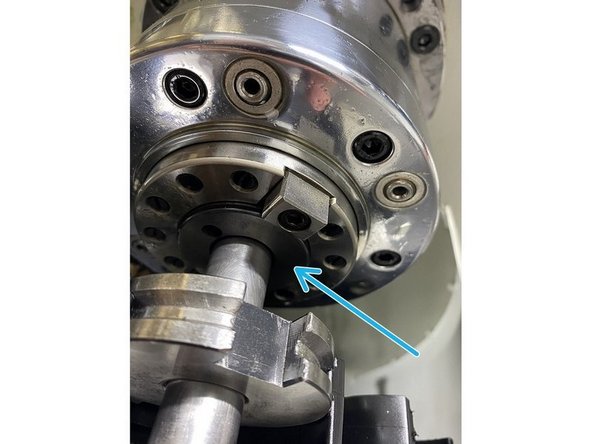
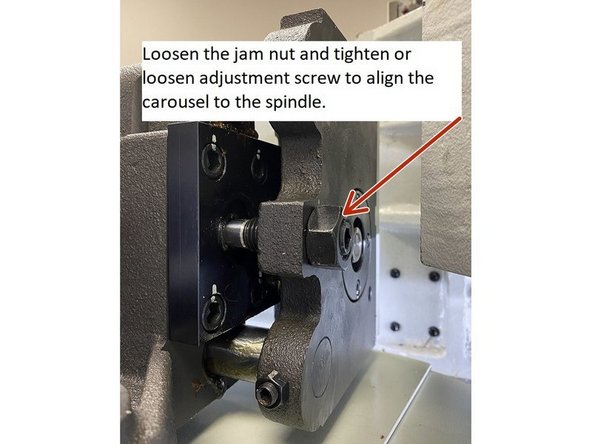
If the carousel only needs a minor alignment in the X Axis loosen the jam nut on the adjustment screw of adjustment point #1 and either tighten or loosen the screw depending which direction the carousel needs to move to align the ring tool with the taper tool in the spindle.
-
You may find it easier to raise the Z Axis to max travel so there is more room to get the Allen wrench onto the adjustment screw while making adjustments and then lowering back down to check alignment.
-
Once the carousel is aligned to the spindle hold the alignment screw with the Allen wrench and tighten the the jam nut then recheck the alignment to make sure nothing changed when the jam nut was tightened.
-
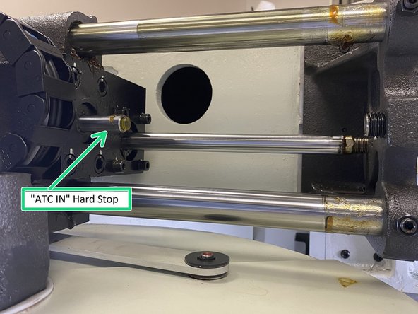
After the carousel to spindle alignment has been completed you should verify that the "ATC IN" limit switch adjustment hasn't changed. Raise the spindle up to max travel and run the carousel in and out a few times to see if it faults. If there isn't a fault message the switch doesn't need to be adjusted.
-
If there was a fault message when moving the carousel in and out the "ATC In" limit switch needs to be adjusted. The adjuster is located just above ATC alignment point one (1) next to the upper linear guide. Loosen the jam nut and adjust so that the limit switch trips when the ATC is all the way out. Tighten the jam nut and test again.
-
If the ATC can't be aligned using alignment point #1 alone, go back to step 5 and go through the full alignment procedure. If ATC is in proper alignment reinstall covers that were removed and clean up.
-
Almost done!
Finish Line


