
-
-
Place adapter plate (p/n 28057) on table as shown and install home indicator block (p/n 28061) using a 10-32x1/2 25B socket head cap screw
-
Lubricate o-rings with white bearing grease prior to installation in adapter plate. Install the following O-rings into the adapter plate: (6) p/n 27805-8, (1) p/n 27805-12, and (1) p/n 27805-9.
-
Align adapter to cycloidal drive and install (6) SHCS M10-1.5x30 25B screws. Apply a light coat of ISO-32 oil on screws prior to installation. Secure screws hand tight but do not torque them down. (This is done during test and alignment).
-
Using the hoist, lift assembly and place on bottom (as needed depending on your set up.) Do not lift heavy objects without proper tools.
-
-
-
Using a 0.0001” indicator, magnetic base, and paper underneath the base (to avoid scratching the paint), measure the “runout” on the adapter plate surface shown below. The “runout” cannot exceed 0.0008” (0.02 mm).
-
If “runout exceeds 0.0008” then loosen the six SHCS M10-1.5x30 25B screws in the face of the adapter plate and tap the adapter plate using the dead-blow hammer and a ¾” diameter aluminum bar, (threading blank for lathes) until the desired “runout” is achieved.
-
After the adapter plate “runout” is within tolerance, use a torque wrench to tighten the screws in the pattern as shown below to 15 ft-lbs, then to 35 ft-lbs, and finally to 50 ft-lbs following the same pattern each time. Verify that the adapter plate “runout” is still within tolerance after torqueing down the screws.
-
-
-
Secure chuck (p/n 27062-2) to adapter plate by hand tightening (3) M10-1.5X80 25B screws.
-
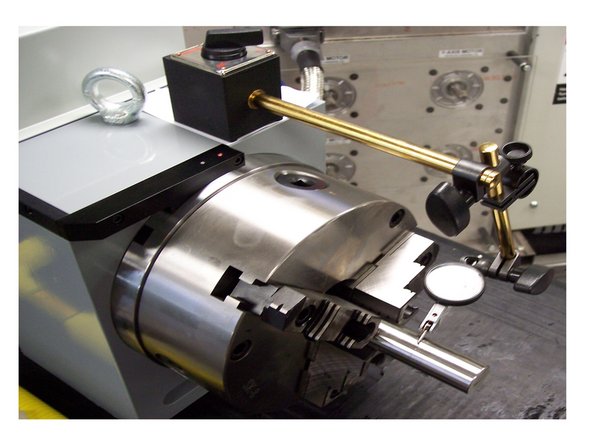
Install the test piece into the chuck as pictured below with one line of the test piece even with the face of the chuck. Use the included T-handle to secure the chuck jaws around the test piece.
-
Using a 0.0001” indicator and magnetic base, position the indicator just behind the front line on the test piece and measure the “runout” of the chuck. The “runout” cannot exceed 0.0008”.
-
If “runout exceeds 0.0008,” then loosen the three M10-1.5X80 25B screws in the face of the chuck and tap the chuck using the dead-blow hammer until the desired “runout” is achieved. When “runout” is adjusted within specification, tighten the chuck by torqueing the M10-1.5X80 25B screws to 25 ft-lbs.
-
Verify that the “runout” is still within tolerance after the screws have been torqued down. Remove the test piece from the chuck jaws using the included T-handle. Remove the magnetic base from the UUT and put the dial indicator back in its protective case.
-


Cancel: I did not complete this guide.
One other person completed this guide.