-
-
The following service codes must be performed when a motor is replaced. Tool change heights will be off in the Z axis and should be adjusted. The machine may crash if these items are not set correctly.
-
Service Code 505 – Reset the motor index angle (machine may not home properly) and reset soft limits. Must be redone after any motor is removed.
-
Service Code 501 – Reset the tool change height. Performed after Z motor axis removed.
-
-
-
Center the X and Y axis and Press the E-STOP. Remove the screws that secure the way covers for the right side of the X-axis. Collapse way covers and remove.
-
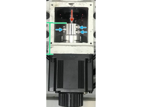
Remove the coupling cover. Rotate the coupling towards the ballscrew until the slot is at twelve o'clock. This will allow you to access the screws from the three o'clock and nine o'clock position.
-
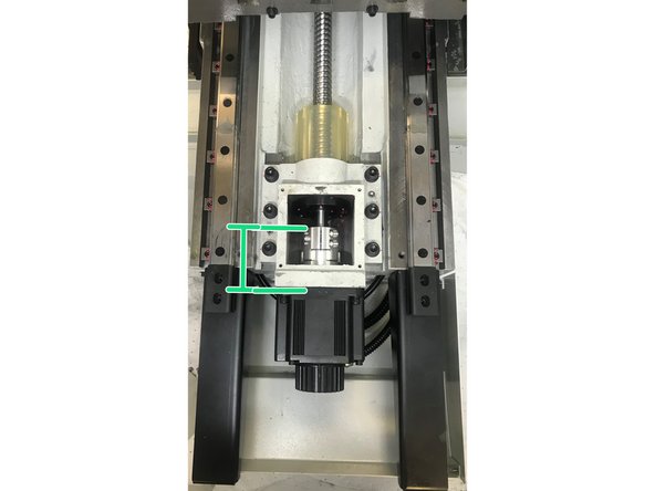
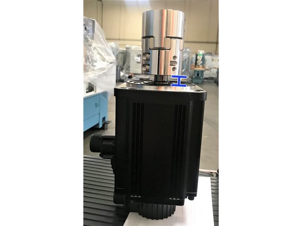
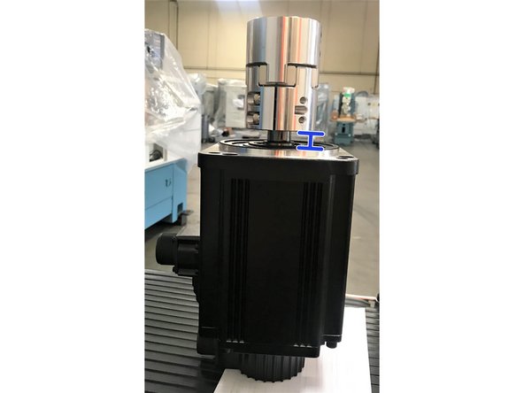
Use scale or caliper to measure distance from coupling edge on ballscrew side to the motor casting and take note of the measurement as shown.
-
Loosen the two M6 lock screws and tighten the set screw. This will release the tension from the shaft.
-
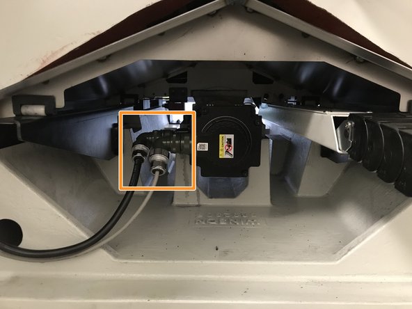
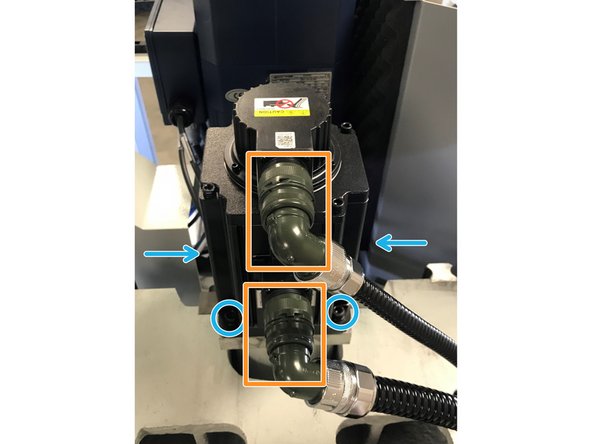
Remove the X-motor cables from the motor itself.
-
Remove the 4 bolts that secure the motor to the motor mounting bracket.
-
-
-
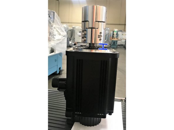
Remove the motor. Note the measurement from the motor to the coupler.
-
Then remove coupler from motor shaft, examine the polyurethane spider element for excessive wear (There should be no visible backlash) If it is suitable for reuse, install it onto replacement motor shaft.
-
Install the replacement motor. Set coupler distance from motor casting to the coupler far edge using your recorded measurement. Install the 4 bolts and tighten to 30 ft lbs.
-
Perform steps in reverse order.
-
Enable servos, perform Service Code 505, slowly jog X axis into X Axis hard stop. Back out one ballscrew revolution and adjust home switch to trigger. Adjust index angle to 180 degrees +/- 40 degrees at 0.500” from hard stop.
-
-
-
Jog the Y-axis to the positive max travel. E-Stop machine and disconnect mill power.
-
Y-axis access to the motor may require sliding the rear most way cover forward after removing way covers from inside the machine. Rotate the coupler towards the ballscrew until the slot is at twelve o’clock and you have access to the three o'clock and nine o'clock position.
-
Use scale or caliper to measure distance from coupler edge on ballscrew side to the motor to motor casting and take note of the measurement.
-
Loosen the two M6 lock screws and tighten the set screw. This will release the tension from the shaft. . Y-axis may require touching as a reference or use of a mirror to complete this task.
-
Remove the Y-motor cables from the motor itself.
-
Remove the 4 bolts that secure the motor to the motor mounting bracket.
-
-
-
Remove the motor. Note the measurement from the motor to the coupler.
-
Then remove coupler from motor shaft, examine the polyurethane spider element for excessive wear (There should be no visible backlash) If it is suitable for reuse, install it onto replacement motor shaft.
-
Install the replacement motor. Set coupler distance from motor casting to the coupler far edge using your recorded measurement. Install the 4 bolts and tighten to 30 ft lbs.
-
Perform steps in reverse order.
-
Enable servos, perform Service Code 505, slowly jog X axis into X Axis hard stop. Back out one ballscrew revolution and adjust home switch to trigger. Adjust index angle to 180 degrees +/- 40 degrees at 0.500” from hard stop.
-
-
-
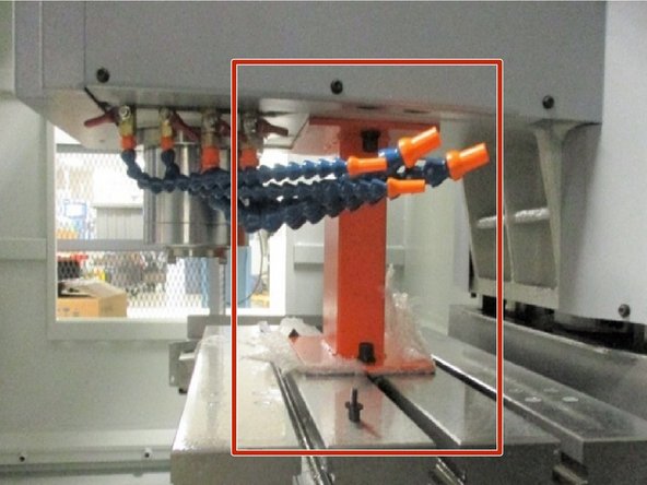
Place foam and/ or wood to protect the table. Center the X and Y axis and raise the Z-axis up giving clearance to place the head support underneath as shown. Lower the Z-axis to the head support. Press the E-stop and turn off power to the machine.
-
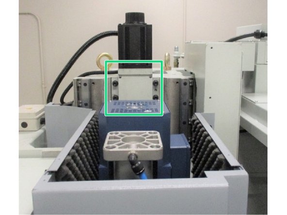
Remove the coupler cover from the motor mounting bracket located behind the spindle drive motor. The coupler slot should be facing outward toward the front of the machine.
-
Rotate the coupling until the slot is at twelve o'clock. This will allow you to access the screws from the three o'clock and nine o'clock position.
-
Use scale or caliper to measure distance from coupling edge on ballscrew side to the motor casting and take note of the measurement as shown. Loosen the two M6 lock screws and tighten the set screw. This will release the tension from the shaft.
-
Remove the Z-motor cables from the motor itself.
-
Remove the 4 bolts that secure the motor to the motor mounting bracket.
-
-
-
Remove the motor. Note the measurement from the motor to the coupler.
-
Then remove coupler from motor shaft, examine the polyurethane spider element for excessive wear (There should be no visible backlash) If it is suitable for reuse, install it onto replacement motor shaft.
-
Install the replacement motor. Set coupler distance from motor casting to the coupler far edge using your recorded measurement. Install the 4 bolts and tighten to 30 ft lbs.
-
Perform steps in reverse order.
-
Enable servos, perform Service Code 505, slowly jog Z axis into Z Axis hard stop. Back out one ballscrew revolution and adjust home switch to trigger. Adjust index angle to 180 degrees +/- 40 degrees at 0.500” from hard stop. Set the tool change height, perform service code 501.
-
Almost done!
Finish Line


