Introduction
This guide is for TMCs manufactured approximately before November 1, 2021, which also have the following serial number formats:
- xxxEMxxxx (TMC5)
- xxxENxxxx (TMC7)
- xxxEPxxxx (TMC10)
These machines do not have the necessary spindle or space to mount the CTS components. This is a complex process to add both a new CTS capable spindle, as well as the CTS components.
If instructions for adding CTS to a newer CTS Ready TMC are needed, see TMC - Add CTS to CTS Ready Machine available on TRAK Dozuki public site.
-
-
TRAK offers a Coolant Through Spindle (CTS) Option. This provides the user with abundant coolant [or cutting fluid] right at the cutting surface to allow for high production speeds and aggressive feeds. It also keeps the coolant focused right where it is needed.
-
Our CTS option can be used with collet-mounted tooling or with drilled tooling, once a CTS compatible retention knob is installed in the tool holder.
-
Coolant is supplied from the coolant tank behind the TMC. A large, high-volume pump is part of the CTS option, which provides ample coolant volume at the work area directly through the spindle.
-
-
-
While facing the back of the machine, remove the circular plate over the coolant tank that is located at the bottom left of the machine.
-
Install the Pump Riser over the circular hole by securing it with four bolts around each of its bottom corners.
-
Install the CTS Pump over the Pump Riser by securing it with four SHCS screws.
-
The CTS Pump with the Impeller weigh about 100 lbs. Have at least two people to lift the CTS Pump properly over the Pump Riser, or use a hoist.
-
-
-
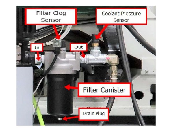
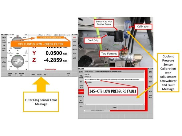
The CTS option has two sensors (Filter Clog Sensor and Coolant Pressure Sensor) and a filter.
-
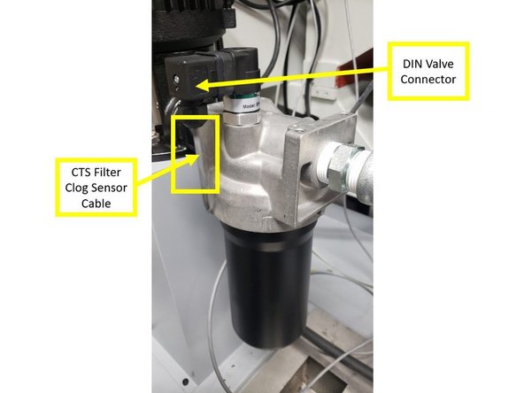
The Filter Clog Sensor is mounted to the filter body. The Coolant Pressure Sensor is installed on a pipe tee that is connected to the right side of the filter assembly. See first image on the left for the location of the two sensors and the filter.
-
The Filter Clog Sensor is designed to detect when the filter canister is clogged, and needs a replacement filter. The sensor detects a pressure differential between the fluid “In” pressure and the fluid “Out” pressure.
-
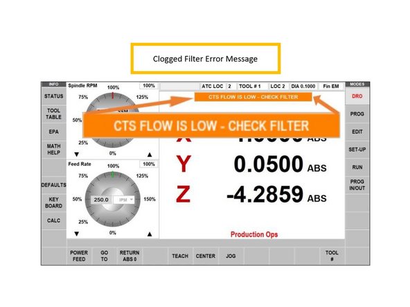
The standard PSI for the fluid "In" pressure varies based on the tool being used. If the pressure differential between “In” and “Out” is greater than 50 PSI, then the sensor displays a warning message on the pendant.
-
The Coolant Pressure Sensor checks for proper coolant pressure in the spindle. The Coolant Pressure Sensor is designed to stop the spindle if the pressure goes below the safety level. It monitors the coolant pressure in case of coolant runout or equipment failure. We’ll be setting this sensor later.
-
There is a warning message displayed on the pendant to give the operator a chance to correct the problem. If this warning message is triggered, the sensor halts the current program, and stops the spindle.
-
-
-
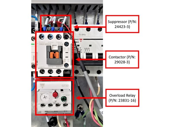
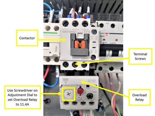
The CTS setup in the electrical cabinet will consist of the Contactor (P/N: 29028-3), the Suppressor (P/N: 24423-3), and the Overload Relay (P/N: 23821-16). Please see first image on the left for reference.
-
Suppressors are inserted in AC units to prevent damage to the equipment due to spikes in voltage.
-
Contactors are used for switching an electrical circuit on or off, and they provide a level of isolation away from high electrical currents, which protects workers and equipment.
-
Overload Relays are designed to protect AC circuits and motors against overloads, phase failure, long starting times, and prolonged stalling of the motor.
-
Install the Overload Relay to the Contactor as shown on the second image on the left. Once the Contactor is properly set up with the Overload Relay, make sure that the terminal screws on the Contactor are securely tightened.
-
Use a screwdriver on the adjustment dial to set the Overload Relay to 11.4A (see second image on the left).
-
Install the Suppressor on top of the Contactor, as shown on the first image on the left. Leave the Suppressor Pigtails alone for now.
-
Once the Contactor, the Suppressor, and the Overload Relay are assembled together, install the back of the Contactor to the right side of the bottom DIN rail (under K22) in the electrical cabinet.
-
-
-
Install the P36-OUT CTS Cable Assy (P/N: 31591 Rev B) and the CTS Overload Wire Assy (P/N: 31591-1) between the Contactor, the Overload Relay, and the P36-OUT port on the computer module:
-
Make sure that you are using Rev B or higher of the above P36-OUT CTS Cable in order to prevent any wiring issues!
-
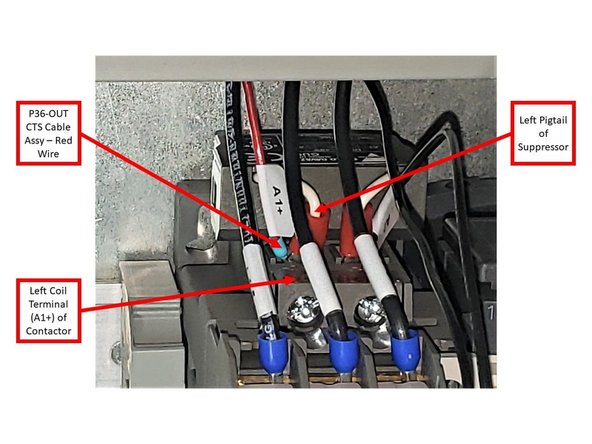
Connect the Left Pigtail of the Suppressor and the Red Wire of the P36-OUT CTS Cable together on the left coil terminal (A1+) of the Contactor.
-
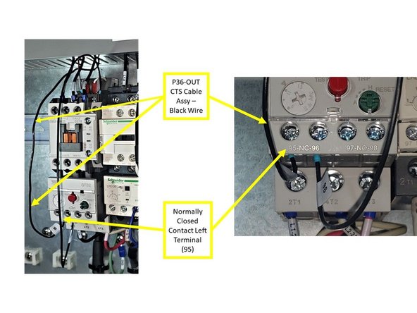
Connect the Black Wire of the P36-OUT CTS Cable to the Normally Closed Contact Left Terminal (95) of the Overload Relay.
-
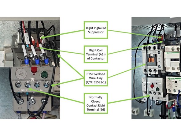
Connect one end of the CTS Overload Wire Assy to the Normally Closed Contact Right Terminal (96) of the Overload Relay, and connect its opposite end together with the Right Pigtail of the Suppressor on the right coil terminal (A2-) of the Contactor.
-
Once the Suppressor Pigtails, the Red and Black Wires of the P36-OUT CTS Cable, and the Overload Wire Assy are correctly installed to both the Contactor and the Overload Relay, make sure that all applicable terminal screws are tightly secured.
-
-
-
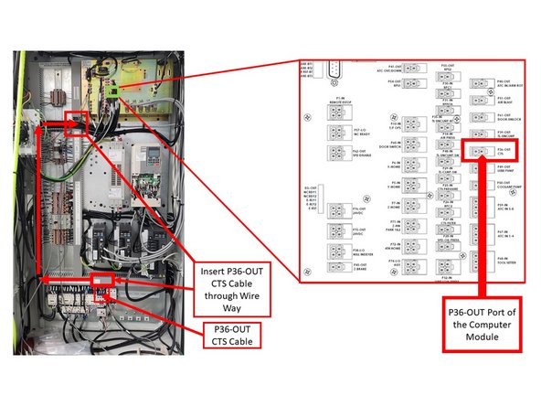
Insert the P36-OUT CTS Cable Assy through the Electrical Cabinet Wire Way (as shown on the second image on the left), and install the opposite end to the P36-OUT port of the computer module.
-
Please refer to Part Number 29100-1 for the location of the P36-OUT port on the computer module; it is included at the bottom of this guide.
-
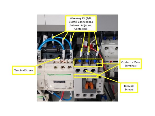
Install each wire of the Wire Assy Kit (P/N: 31597) to their designated areas on the main terminals of the Contactor: install the L1-5 wire to the R/1/L1 terminal; the L2-5 wire to the S/3/L2 terminal; and the L3-5 wire to the T/5/L3 terminal.
-
Insert the opposite ends of each wire of the Wire Assy Kit through the wire way, and install them on their designated terminals on the adjacent Contactor to left (labeled as K11): install the L1-5 wire to the 1L1 terminal; the L2-5 wire to the 3L2 terminal; and the L3-5 wire to the 5L3 terminal (see image).
-
Once the Wire Assy Kit had been properly installed on both contactors, make sure that the terminal screws on both contactors are tightly secured as well.
-
-
-
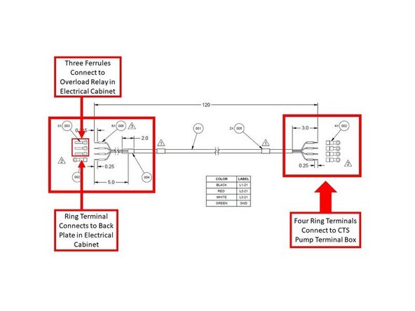
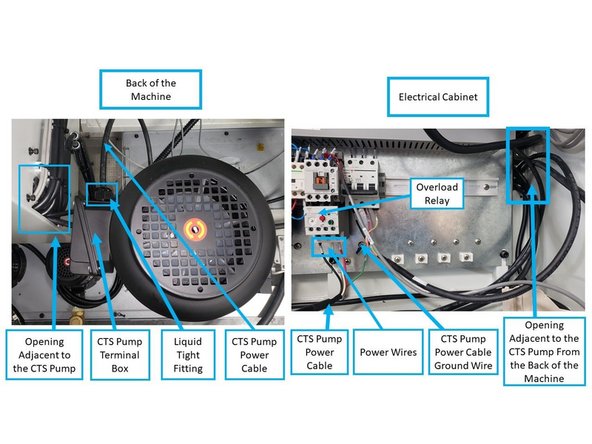
Install the CTS Pump Power Cable (Part Number 31592) from the CTS pump terminal box to the Q21 Overload Relay, and is ground wire to the GS36 location in the electrical cabinet. See first image on the left for a diagram of the CTS Pump Power Cable.
-
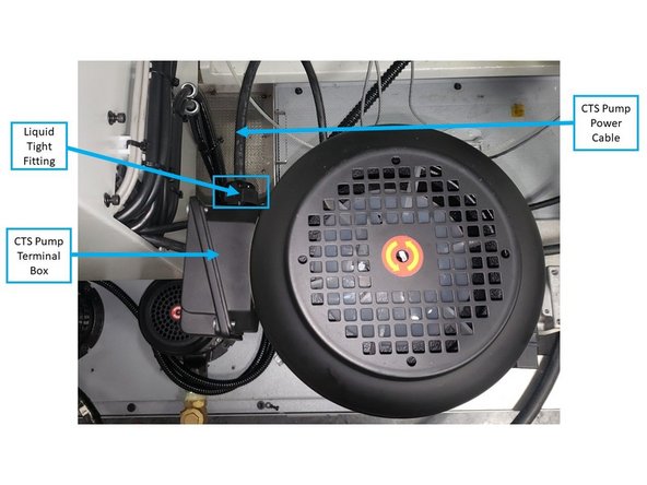
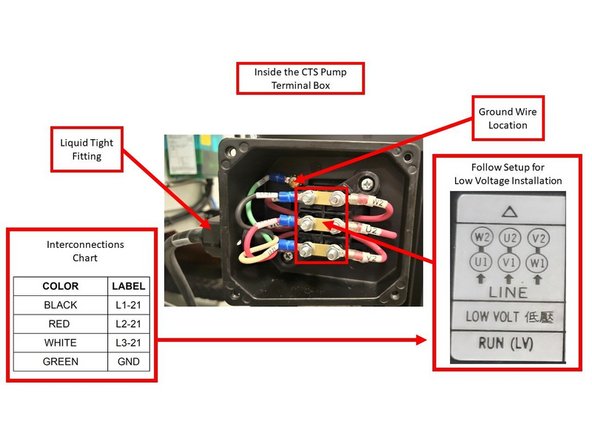
Insert the end of the CTS Pump Power Cable that has four ring terminals (see first image on the left) to the CTS Pump Terminal Box through the new liquid tight fitting (Part Number 31696). Install the combined liquid tight fitting and CTS Pump Power Cable on the terminal box itself.
-
On the opposite end of the CTS Power Cable, connect the power wires to their corresponding terminal screws and ground to chassis on the electrical cabinet (see first image on the left).
-
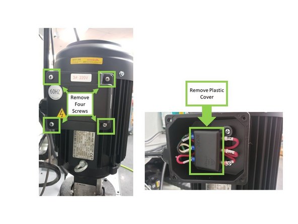
Open the terminal box by removing the four screws around each corner of the terminal box cover. Once removed, also remove the plastic cover that covers the wiring inside the terminal box.
-
-
-
There will be pink wires coming from within the terminal box with the following labels: U1, U2, V1, V2, W1, and W2, along with label instructions for both high and low voltage installation. Per the first image on the left, follow the instructions for low voltage installation:
-
Top row: combine the black wire (L1-21) with the pink U1 wire on the left, and set the pink W2 wire on the right. Second row: combine the red wire (L2-21) with the pink V1 wire on the left, and set the pink U2 wire on the right. Bottom row: combine the white wire (L3-21) and the pink W1 wire on the left, and set the pink V2 wire on the right.
-
While facing the back of the machine, insert the opposite end of the CTS Pump Power Cable through the opening adjacent to the CTS Pump, and into the electrical cabinet (see third image on the left).
-
Install the CTS Pump Power Cable in the following manner (see image on the left):
-
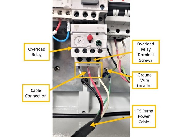
Install the black wire (L1-21) to the "2T1" slot on the Overload Relay; red wire (L2-21) to the "4T2" slot, and the white wire (L3-21) to the "6T3" slot.
-
Install the ring terminal (ground wire) to its designated location on the electrical cabinet.
-
-
-
The following process details how to connect the CTS Filter Clog Sensor Cable to the computer module inside the electrical cabinet.
-
The Part Number for the CTS Filter Clog Sensor Cable is P/N 31593.
-
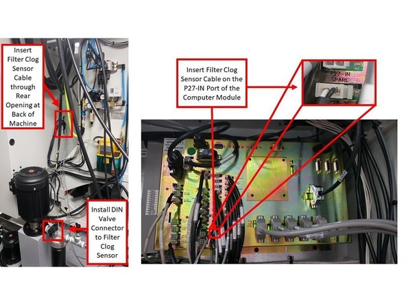
Install the end of the CTS Filter Clog Sensor Cable that contains the DIN Valve Connector to the sensor itself. Secure the DIN Valve Connector to the sensor with a Philips screw.
-
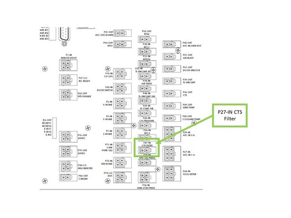
The opposite end of the CTS Filter Clog Sensor Cable enters the cabinet from behind on the inner corner mount with chassis along with other signal cables. Connect it to the port labeled as "P27-IN" on the computer module inside the electrical cabinet.
-
Please see third image on the left for the location of the P27-IN port on the computer module; it is also included on the Part Number 29100-1 document that is attached at the bottom of this guide.
-
-
-
The following process details how to connect the CTS Coolant Pressure Sensor Cable to the computer module inside the electrical cabinet.
-
The Part Number for the CTS Coolant Pressure Sensor Cable is P/N 31594.
-
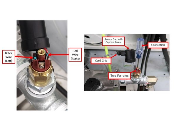
Connect the end of the Coolant Pressure Sensor Cable that contains the red and black wires to the sensor itself. Install the red wire on the right connector, and the black wire on the left connector.
-
Using a screwdriver, secure the captive screw over the sensor cap at the top of the sensor. Do not tighten the cord grip yet, because the Coolant Pressure Sensor still needs to be calibrated at a later step.
-
The opposite end of the Coolant Pressure Sensor Cable enters the cabinet from behind on the inner corner mount with chassis along with other signal cables. Connect it to the port labeled as "P25-IN" on the computer module inside the electrical cabinet.
-
Please refer to Part Number 29100-1 for the location of the P25-IN port on the computer module; it is included at the bottom of this guide.
-
-
-
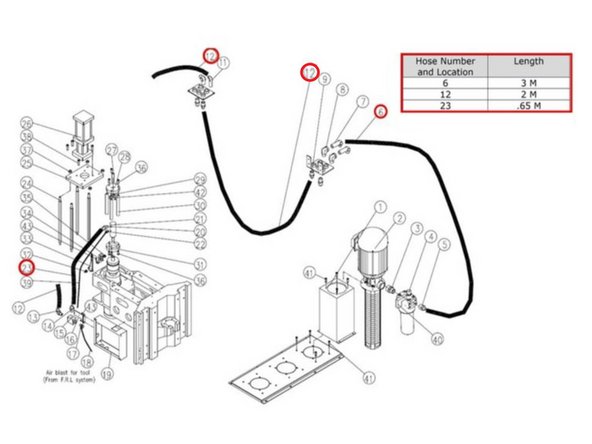
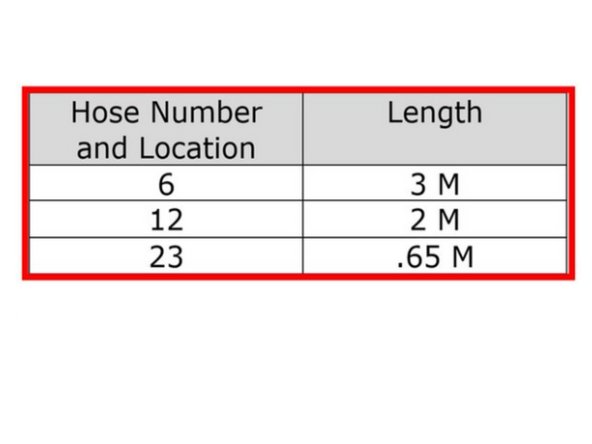
Photo is labeled as to the location of each CTS coolant line hose. The chart gives the correct length for each location.
-
The following are the Part Numbers for the CTS coolant hoses:
-
3 M CTS Hose Coolant (P/N: 31572)
-
1.6 M CTS Hose Coolant (P/N: 31573)
-
2 M CTS Hose Coolant (P/N: 31574)
-
.65 M CTS Hose Coolant (P/N: 31578)
-
-
-
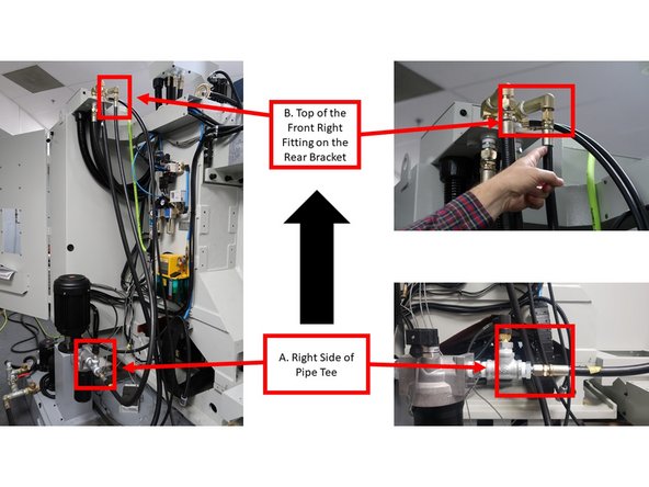
While facing the back of the machine, route coolant lines by installing a 3 m hydraulic hose on the right side of the pipe tee that also houses the Coolant Pressure Sensor (labeled as "A" on the first left image), and installing the other end to the top of the front right fitting on the rear bracket (labeled as "B" on the first left image).
-
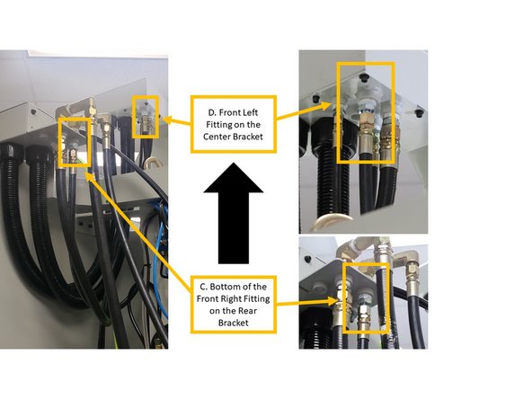
From the rear bracket, continue the coolant line by installing a 1.6 m hydraulic hose at the bottom of the front right fitting (labeled as "C" on the second left image), and installing the other end to the front left fitting on the center bracket (labeled as "D" on the second left image).
-
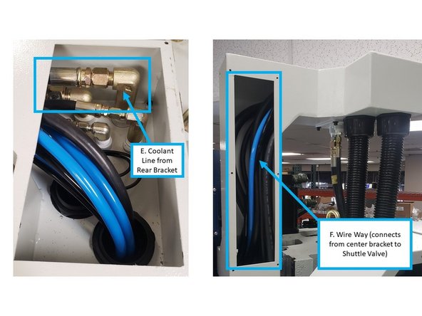
From the front right fitting within the center bracket (see top view of center bracket that is labeled as "E" on the third image on the left), direct the coolant line by installing a 2 m hydraulic hose through to the wire way (labeled as "F" on the third image on the left).
-
-
-
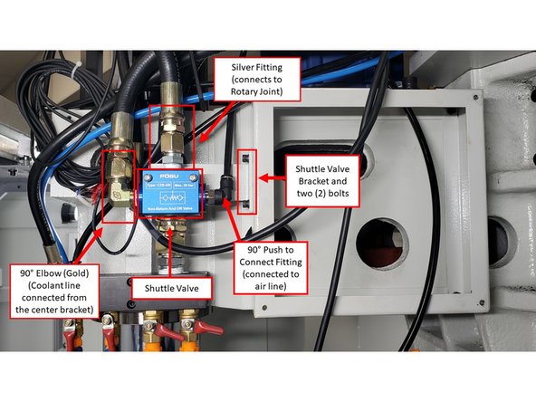
While facing the front of the machine, install the Shuttle Valve and its bracket on the right side of the sheet metal above the spindle.
-
Install the bracket on the sheet metal with two bolts, and then install the Shuttle Valve itself onto the bracket with two bolts. Some machines may need the sheetmetal box drilled and tapped. Future machines will come with holes pre-drilled.
-
The Shuttle Valve has three points of connection:
-
Install a 90° elbow (gold) on the left side of the Shuttle Valve in order to connect it to the coolant line that is coming from the center bracket through the wire way.
-
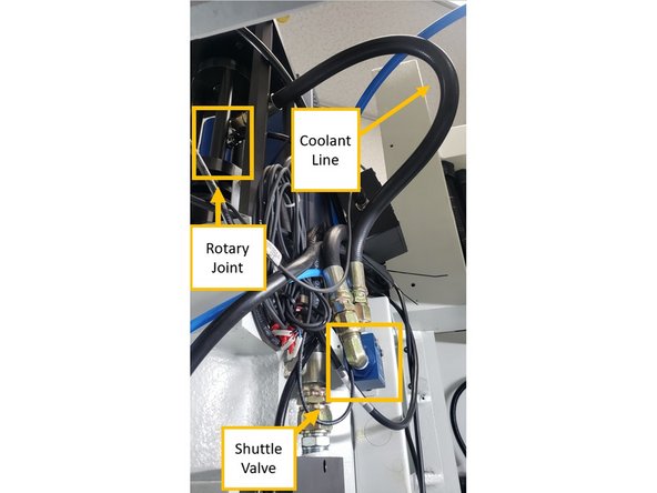
On the top of the Shuttle Valve, install a silver fitting that will continue the coolant line from the Shuttle Valve to the Rotary Joint.
-
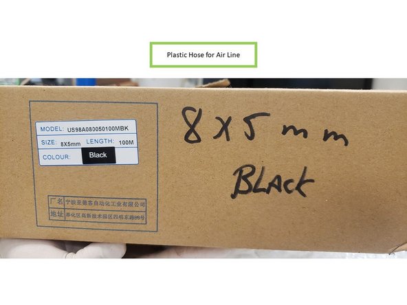
On the right side of the Shuttle Valve, install a 90° Push to Connect fitting in order to connect the Shuttle Valve to the air cylinder above the spindle.
-
Please note that the plastic hose connecting the Shuttle Valve to the air cylinder will need to be replaced by a longer hose; the hose that comes with the kit may be too small. An available spool of the plastic hose is located in the Big Room above the parts cabinet; cut to length for the appropriate size.
-
-
-
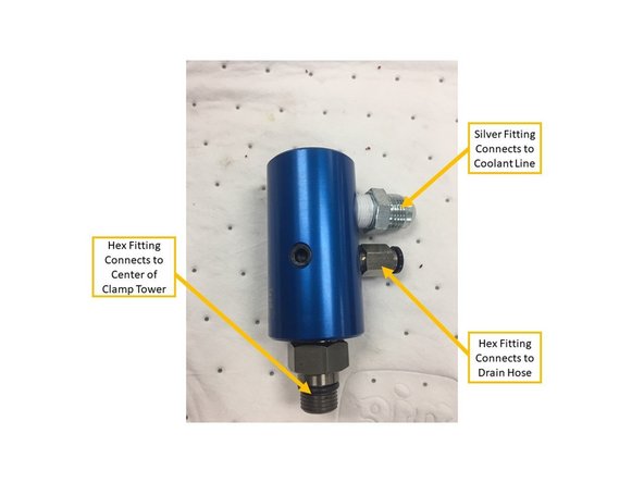
The Rotary Joint connects the coolant line to the top of the spindle, which allows coolant to flow down through the spindle and into the cutting tool.
-
Prepare the Rotary Joint by installing the correct fittings on it as shown on the first image on the left. Per the image, the top silver fitting connects to the coolant line, the hex fitting directly below connects to the drain hose, and the hex fitting at the very bottom connects to the center of the clamp tower on top of the piston.
-
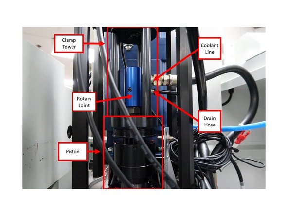
Install the Rotary Joint at the center of the clamp tower above the piston on top of the spindle. Tighten snugly by hand to approximately 15ft-lbs. Use an adjustable wrench on spindle dogs to hold spindle from rotating.
-
The Rotary Joint is a left-handed thread.
-
Insert the coolant line by installing a 0.65 hydraulic hose on the silver hydraulic fitting on the Rotary Joint itself.
-
On the hex fitting below the coolant line, attach the drain hose to the Rotary Joint, and route its opposite end to the sheetmetal box on the right side of the casting.
-
-
-
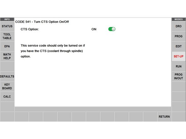
Service Code 541 allows users to turn the CTS Option on and off.
-
Service Code 541 should only be turned on for machines actually have the CTS option! Otherwise, do not turn on this Service Code because it will cause issues with the machine.
-
Service Code 541 can be readily accessed on new machines. It can also be accessed with machines that have the updated software Version 2.4.0 or later.
-
Turning on Service Code 541 enables the monitoring capabilities of the Filter Clog Sensor and Coolant Pressure Sensor (as mentioned in Step 3 of this guide). It also enables the use of the CTS On/Off hard key button on the pendant.
-
-
-
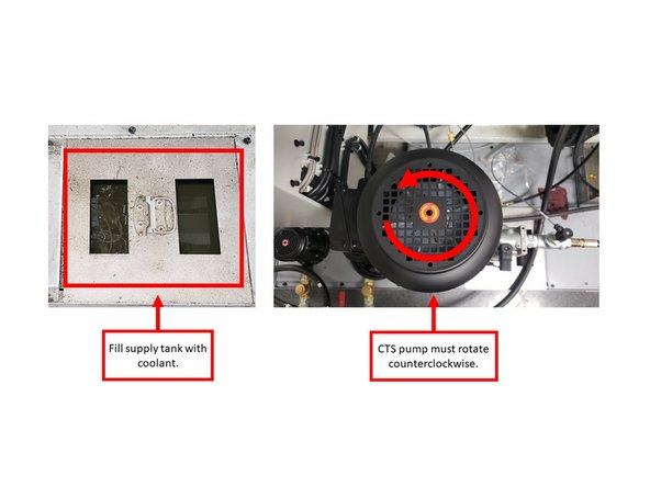
Fill the supply tank with coolant and turn on CTS at the pendant. Make sure that the CTS pump is rotating in the correct direction (counterclockwise). There is an arrow on the motor to check this.
-
Coolant coming out of the spindle is not an indication that the pump is turning in the proper direction. Observe the direction of the motor fan.
-
Test filter clog sensor. Turn the pump on, and unplug inputs to see the "CTS FLOW IS LOW" message flash on screen (left image). Replace inputs.
-
Calibrate the coolant pressure sensor through the following steps:
-
If the spindle has a tool in it, remove it prior to calibration.
-
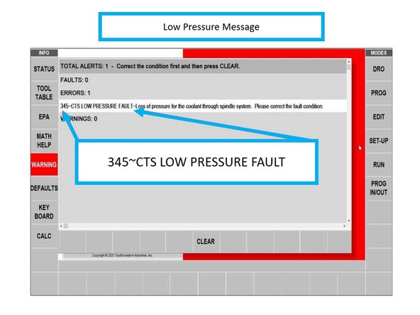
Note the adjustment screwdriver for calibration (upper right image). Using a screwdriver slowly tighten the screw on the top center of the sensor approximately 1/8th of a turn per second.
-
When the machine faults out (lower right image), loosen the screw ¼ turn, and clear the fault on the pendant.
-
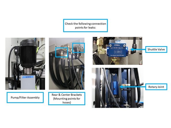
Run the CTS pump for 10 minutes, and check the following connection points below for leaks: pump/filter assembly, both mounting points for hoses (center and rear brackets), shuttle valve, and rotary joint on spindle. The spindle does not need to be turned on during this process.
-
-
-
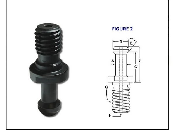
Our CTS option can be used with collet-mounted tooling or with drilled tooling, once a CTS compatible retention knob is installed in the tool holder.
-
The TMC5/7/10 uses CAT40 retention knobs. If the CTS option is purchased for the TMC5/7/10, you will need retention knobs similar to TMC5/7/10, but with holes.
-
Retention knobs for the CTS Option can be purchased through TRAK Machine Tools under part number: 26804-1.
-
![TRAK offers a Coolant Through Spindle (CTS) Option. This provides the user with abundant coolant [or cutting fluid] right at the cutting surface to allow for high production speeds and aggressive feeds. It also keeps the coolant focused right where it is needed.](https://d3t0tbmlie281e.cloudfront.net/igi/trakmtsupport/lV5Vcg4sMtLVFTjB.medium)