Introduction
This guide shows photos from various models of TMCs for illustration purposes. Models have different table weights; however, these instructions apply to all models.
-
-
Check squareness of X axis T-Slot. Set up indicator in spindle, touch off indicator on side of T-Slot. Move X axis full travel and note runout.
-
Remove 4 way covers from X axis table. Remove Left and Right side way covers, remove front and rear way covers.
-
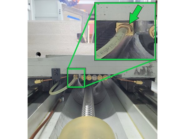
Remove 6mm nylon lube line from X axis manifold. Manifold is under left side of X axis.
-
Remove 2 SHCS from energy chain bracket.
-
-
-
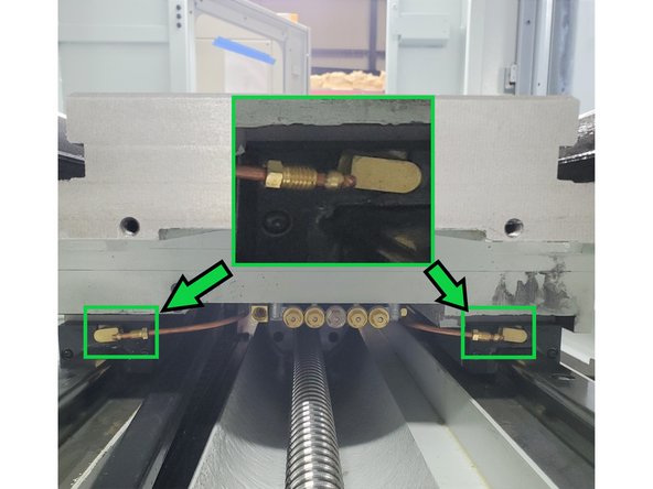
Remove 4mm copper oil lines going to each bearing block.
-
Remove (5) 8mm SHCS from Ball Screw flange at yoke.
-
Carefully slide X axis table to the right approximately 6”. This will position the table so that the horse shoe shaped yoke will clear the Ball Screw. Do not lift table with Ball Nut in Yoke.
-
-
-
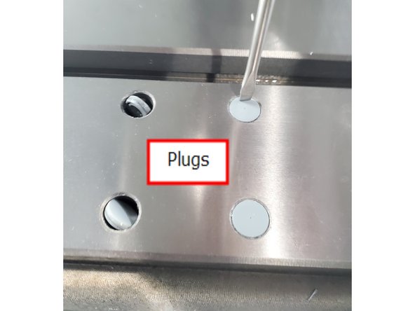
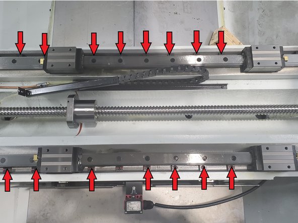
Carefully remove (16) counter bore plugs by lightly taping the edge of plug. The plugs will rotate in counter bore, remove with needle nose pliers. Save plugs to re-install.
-
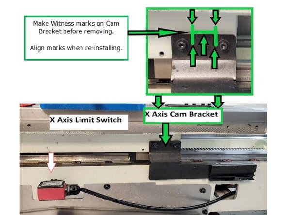
Remove X axis Limit Switch Cam Actuator bracket assy. Mark location of bracket to facilitate re-installing in correct location.
-
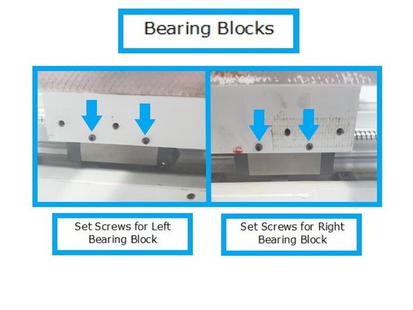
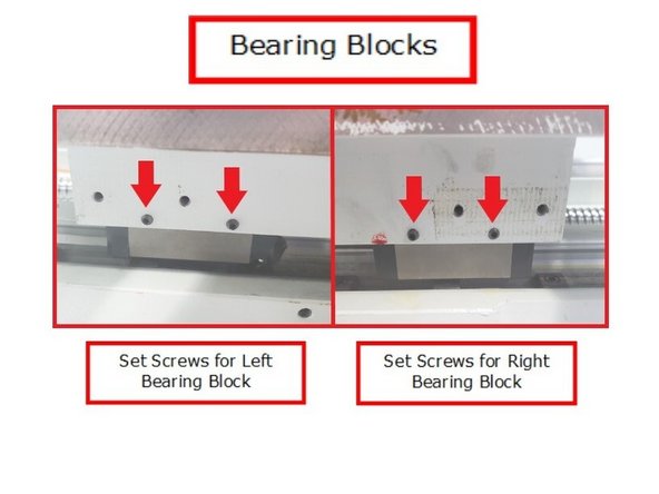
Loosen (4) set screws for front Left and front Right bearing blocks.
-
-
-
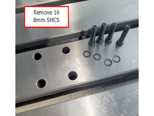
Remove (16) 8mm SHCS and serrated washers from all 4 Bearing Blocks.
-
Position table for removal. Make sure Yoke is clear of Ball Screw nut. Note: Table is wider than the front door opening (TMC10). Lift table with (4) Eye bolts, T-Nuts and straps. Make sure not to hit Ball Screw with Yoke when lifting table. Ensure straps are rated to accommodate the weight of the table.
-
If removing from front, the table will have to be rotated slightly after lifting to clear doors. Suggest lifting table from RHS Door if possible.
-
-
-
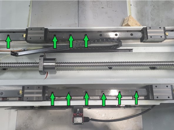
Wedge blocks are located along the outside edge of the linear rail. Remove all wedge blocks from front and Rear Linear Guide rails.
-
Remove all caps from Linear Guide rail mounting bolt counter bore holes. Pierce center of cap with awl and pry out. New caps are provided with Linear Guides. (Total of 44 caps)
-
-
-
Safety when lifting is our first concern. We don't want people injured as well as the precision table damaged. Be careful and follow directions.You will lift a very heavy table in close quarters. planning out the job is important.
-
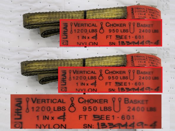
Lifting Kit used for this guide:
-
This kit has two straps rated for 2400 pounds each. Insert shows this strap has a weight limit of 2400 lbs. when used in basket mode. Two straps were used in the lift.
-
For safe lifting, each strap must be in good shape, and should each be (at least) rated for the weight of the table, this will give us 2X the lifting capacity.
-
The straps need to be positioned right up against the step on the bottom of the table, so they do not slip side-to-side and have no chance of slipping off the end of the table,… and they both need to be straight up and down, not at some angle.
-
-
-
Caution!! Approximate Weights: up to TMC 12/14 1200 lbs. Use equipment rated to exceed the weight you are lifting.
-
Suggest the use of a spotter to steady the table while removing it from the mill.
-
The length of straps is important. You need to balance the load and be able to clear the top of the window. Be careful to clear the ball screw, mill and window opening when removing the table.
-
Commercial Fork lifts have normal capacity over 10,000 lbs. Make sure you have the properly rated fork lift with a skilled driver, each strap rated to lift the table, access to the right side of the mill with a fork lift.
-
TMC 12/14 the clearance for the table through the right window is tight.
-
The straps need to be positioned right up against the step on the bottom of the table, so they do not slip side-to-side and have no chance of slipping off the end of the table,… and they both need to be straight up and down, not at some angle. Use two fork lift blades positioned above the table parallel to the edges of the table.
-
-
-
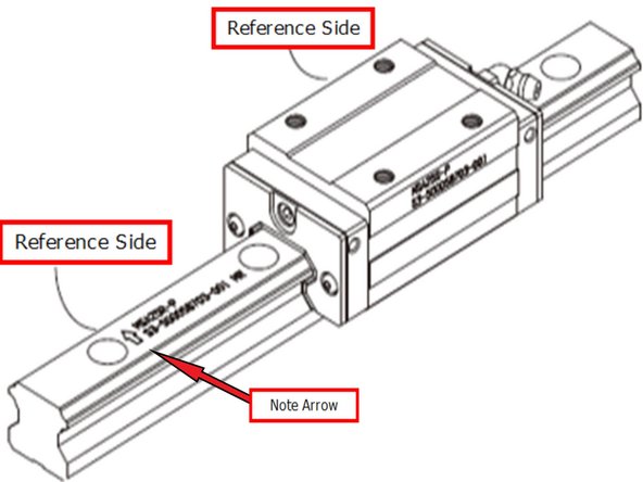
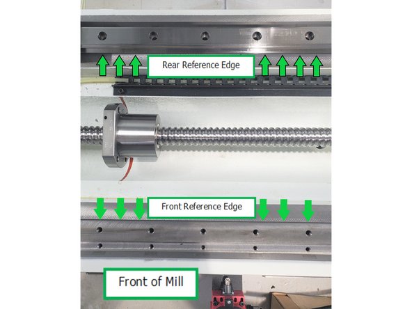
Recognizing of Reference Side of the Linear Guide.
-
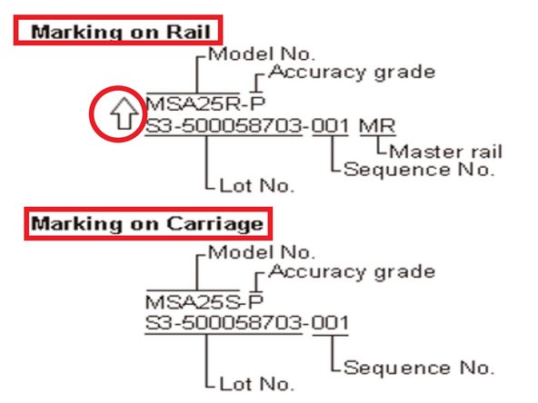
The reference side of the rail is assigned by the arrow sign which is marked together with the model code and lot number on top surface of the rail while that of carriage is the side which is opposed to the side marked with lot number and model code marked, as shown.
-
Lightly stone Linear Guide mounting surfaces and Reference edges of the machine saddle to ensure surfaces are flat and free of burs. Clean and wipe down all mounting and reference surfaces.
-
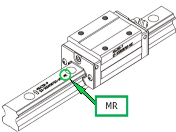
Remove Linear Guides from packaging. Identify the Master and Subsidiary rails. Identify the Reference edges (Arrow). See chart below. The Master rail is identified by a “MR” after the sequence number.
-
-
-
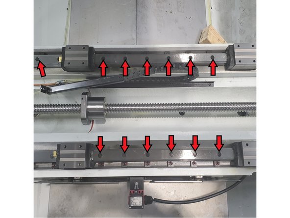
Clean the mounting surface and reference edges of the Subsidiary rail. Carefully place rail on rear mounting surface. Ensure Reference Arrow is facing the front of machine as shown. Install the M8 SHCS into counter bores of rail.
-
Slightly tighten bolts from right to left while pressing the rail against the reference edge. Do not torque the M8 SHCS.
-
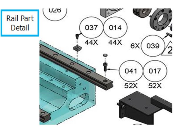
Install wedge blocks. Torque the M6 SHCS to 7 ft.-lbs. working from right to left. Item #37.
-
Torque the M8 SHCS mounting bolts to 15 ft.-lbs. working from right to left. Item #41.
-
Repeat all 4 above steps for the Master Linear Guide. The Reference arrow should be facing the rear of the machine for the Master rail as shown.
-
-
-
Install black caps on both the Master and Subsidiary rails that cover the M8 SHCS mounting bolts. Ensure caps are flush with top of rail.
-
Lift and prepare table for re-installation. Lightly stone all 4 mounting surfaces and reference edges on bottom of table that mount to blocks to ensure they are flat and free of burs. Wipe surfaces clean. Space bearing blocks on rails to match the bolt hole pattern of table.
-
Install 1 M8 SHCS with serrated washer in all 4 corners of table. Use bolts as a reference to align bearing blocks when lowering table down. Make sure yoke clears the Ball Screw nut and does not hit the Ball Screw when lowering table onto bearing blocks.
-
Install the remaining M8 SHCS and washers thru top of table into bearing blocks. Do not tighten M8 bolts.
-
-
-
Tighten the (4) set screws on the front of the table. This will pull the table up against the reference edge of the Master bearing block to the reference edge of the table.
-
Torque all (16) M8 bolts to 25 ft.-lbs. Re-install the copper lube lines to each bearing block. Re-install energy chain bolts. Re-install 6mm nylon lube line to manifold. Carefully slide table up against the Ball Screw flange nut.
-
Make sure the flat of the ball nut is facing down. Install the (5) M8 SHCS bolts into Ball Screw flange to yoke and torque to 25 ft.-lbs. Turn machine on and cycle the lube pump several times to verify no leaks at fittings and way lube is oiling the bearing blocks and guide rails.
-
Re-attach X axis limit switch bracket aligning with the mark made before removing. Re-install caps for mounting bolts on top of table. Ensure caps are flush with top of table.
-
-
-
Home machine and check index angle for X axis. (Index angle must be checked in the positive direction.) Adjust cam as needed to obtain 180 degrees (+) or (–) 45 degrees of 180. Note: If index angle is changed the ball lock locations will need to be reset (LPM Only).
-
Check backlash and adjust if necessary.
-
Check squareness of X axis T-Slot. Set up indicator in spindle, touch off indicator on side of T-Slot. Move X axis full travel and note runout. Runout value should be the same or better than original reading.
-
Re-install all way covers
-


