-
-
In the event of a crash or suspected repeatability issues, checking the turret alignment is necessary.
-
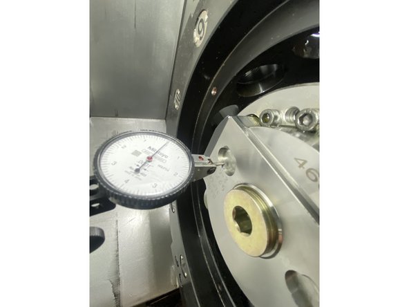
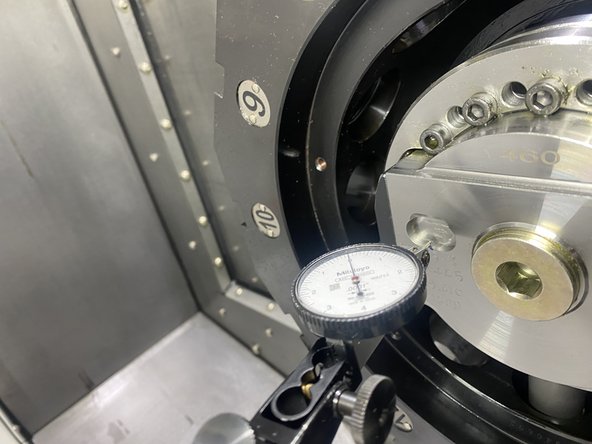
To check turret alignment, position an indicator along the face of the turret and move it back and forth in the X direction, noting the tram measurements.
-
-
-
Begin by loosening the six 4mm screws on the sheet metal cover at the back of the machine; there’s no need to remove them completely. Slide the cover upward and pull it outward to detach.
-
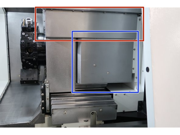
With the main panel removed, locate the specified areas for the 5mm socket head cap screws securing the front panels.
-
Remove the two 5mm socket head cap screws (SHCS) on the left side.
-
Remove the two 5mm socket head cap screws (SHCS) on the right side.
-
-
-
The highlighted covers must be removed to access the locking mechanism for the turret.
-
-
-
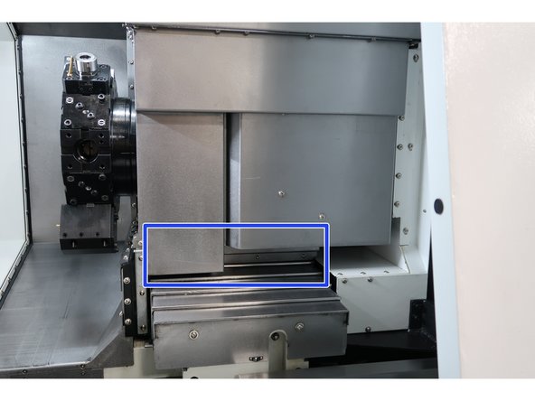
The area needing access is highlighted in blue. The following steps reference this area once the covers have been removed:
-
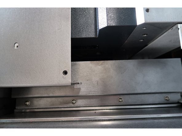
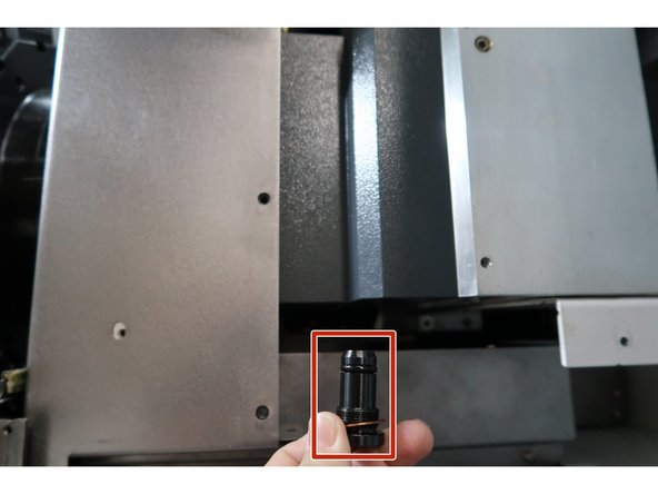
There is a black, threaded plug on the underside that can be removed using a 6mm hex key.
-
Beneath this plug, there is a 5mm hex screw that, when loosened, will allow the turret to move.
-
By tapping the turret with a rubber mallet, small adjustments to the turret's alignment can be made.
-
-
-
Using a tenths indicator, tram the turret using the ground oblong pockets on the face of the disk.
-
Once the turret is tightened down and rechecked for squareness, reinstall the plug and sheet metal.
-
The turret is now aligned.
-
Almost done!
Finish Line


