-
-
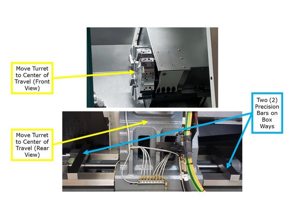
Before you can get started with the Sub Spindle alignment you must be sure the machine is level. If the machine is not level it's bed can become twisted and this can move the machine centers out of alignment. This can make the Sub Spindle appear to be out of alignment. Use the below link to level the machine.
-
Link to level the machine: TRAK TC820si & TRAK TC820LTYsi - Leveling
-
-
-
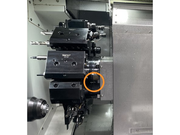
To get started on this procedure remove the tool holders at stations 1 and 7.
-
Set the turret to the number one tool location. Verify the alignment marks are lined up. See Photo 1
-
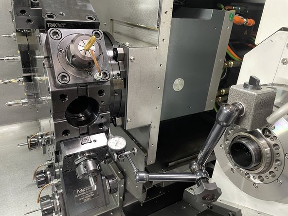
Install a dial indicator on a mag base and attach it to the Z2 spindle assembly. See Photo 2
-
-
-
Before getting started first verify that the turret needs to be realigned.
-
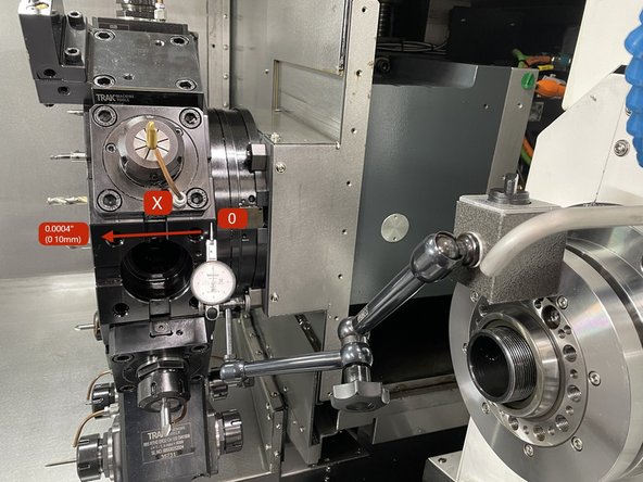
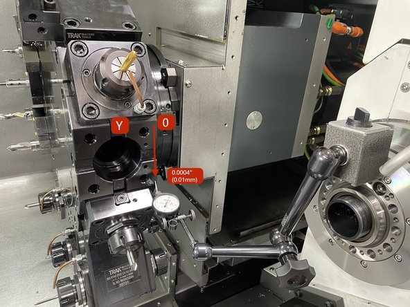
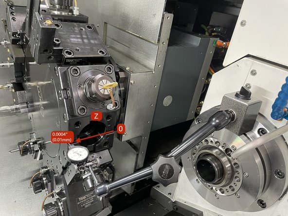
Measure the turret disk on the tool holder mounting face in locations X, Y, and Z. Zero on the right side and measure to the left. The spec is .0004/3.5" (.01/90mm) on all 3 axis. On the Y axis zero at the top and measure down. See photos for axis measurements.
-
If it is determined that the turret is out of alignment the following procedure will assist you in getting it back into alignment.
-
If the Y axis is out of spec the following link is to the procedure on how to realign the turret in that axis.
-
-
-
-
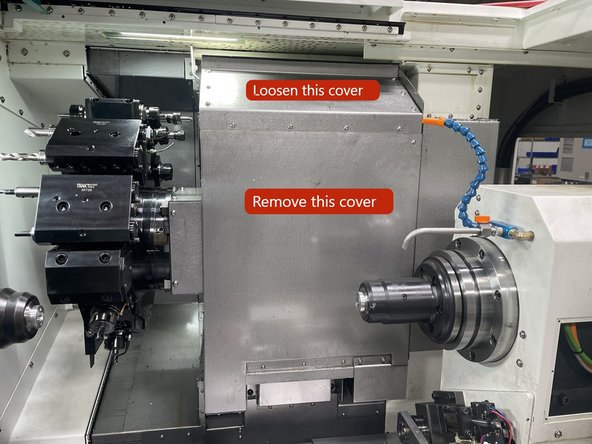
To access the turret there a few covers that need to be removed. The rear 2 covers and the rear right side cover.
-
-
-
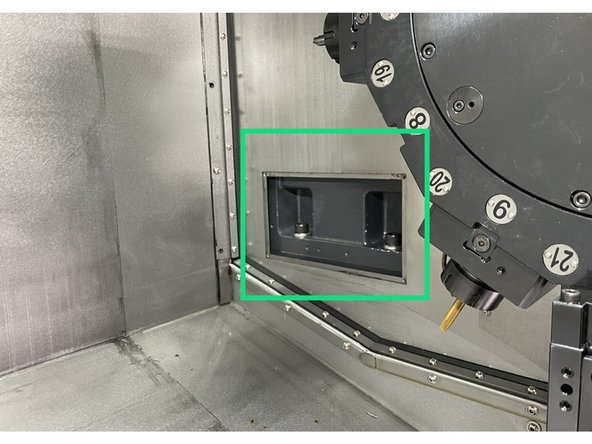
Next you need to remove the inner covers on the turret assembly.
-
Loosen the screws on the upper inner cover and remove the front cover. See Photo
-
Remove the left inside cover.
-
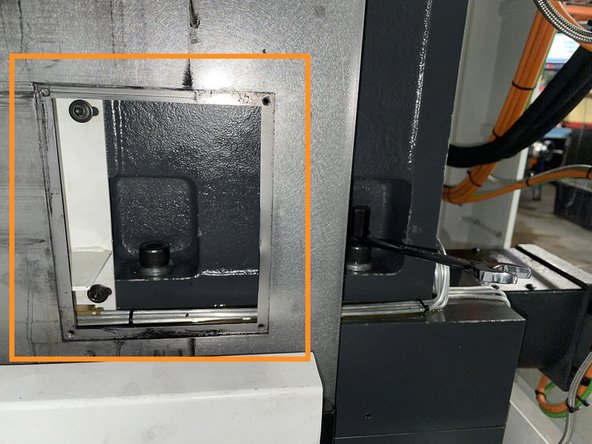
Remove the right side cover from the right rear side of the machine.
-
-
-
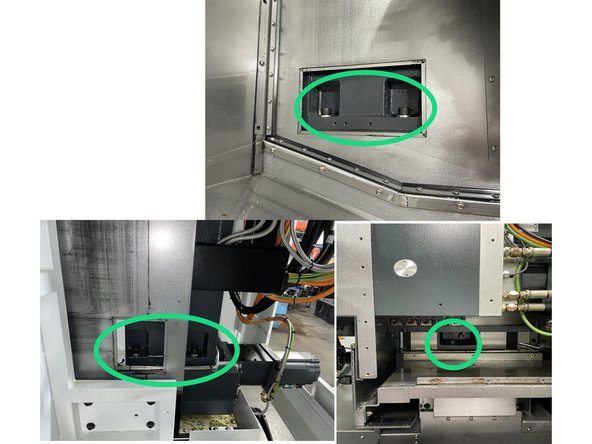
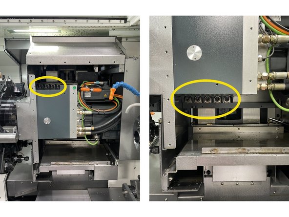
For the horizontal alignment loosen the 5 screws on the y Axis column and retorque to 7 ft-lbs (100kgf). See photo 1 for screw locations.
-
For the vertical alignment loosen the 4 upper and 5 lower screws and retorque to 7 ft-lbs (100kgf). See Photo 3 for screw locations.
-
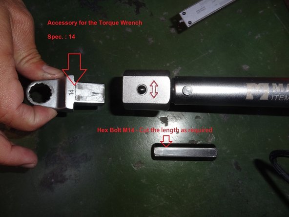
Use a special torque wrench with a 14mm box end wrench and a short cut 14mm hex driver to loosen the 5 screws that attach the Y Axis column. See photo 3 for tools.
-
-
-
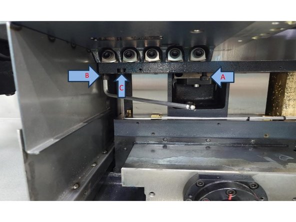
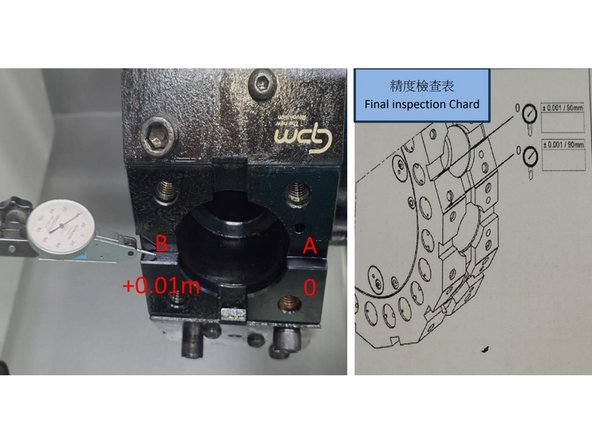
To adjust the vertical accuracy use the screws marked with the arrows in Photo 1. You can loosen C to adjust B or tighten C to adjust A to get the accuracy back to within 0.0004" (0.01mm).
-
After finishing the vertical adjustment of the turret assembly, torque all of the screws to 72 ft-lbs (1000kgf). Then, recheck the accuracy to confirm that it didn't change when the screws were tightened.
-
-
-
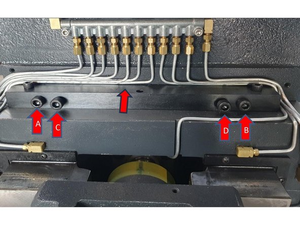
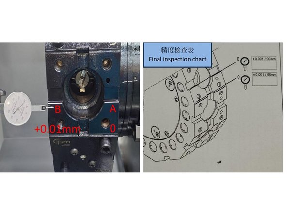
To adjust the Horizontal accuracy use the screws marked A, B, C & D below. You can loosen A to adjust C or loosen B to adjust D to bring the horizontal accuracy back to within 0.0004" (0.01mm).
-
After finishing the horizontal adjustment of the Y axis column, torque all screws to 187 ft-lbs (2600kgf). Then, recheck the accuracy to confirm that it didn't change when the screws were tightened.
-
-
-
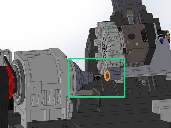
Once the horizontal and vertical accuracy has been aligned you need to check the Spindle to turret centerline concentricity. To do this install a 5C Collet Chuck with a 0.375" High Accuracy Collet.
-
Clean the 5C Collet Chuck with WD-40 or an equivalent, and use a fine grit deburring stone to check for dinks or high spots on the mounting and measuring faces.
-
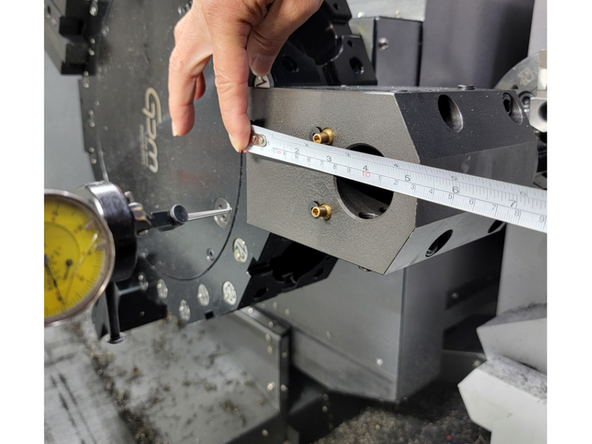
Attach an inspected Boring Bar Tool Holder to the Turret, the offset between the turret face and center of the bore must be known. Install the 5C collet chuck onto the spindle face. Using a high accuracy 5C Collet install a Co-Axial dial indicator so it is centered on the Spindle rotary axis.
-
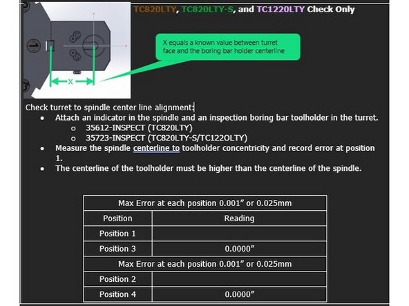
Position the indicator so it is measuring on the ID of the boring bar holder and adjust the axis so the turret is close to the centerline of the spindle. The X-Axis should be at the value equal to the offset between the turret face and the center of the bore on the Boring Bar Holder. The Y-Axis should be positioned on 0.
-
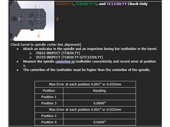
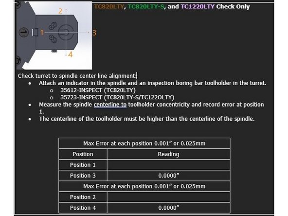
Starting with the digital indicator set to Zero at position 3, rotate the spindle 360° and record the indicator movement at positions 1, 2, and 4.
-
The maximum permitted error is 0.001" [0.025mm]. The centerline of the toolholder in the Y Axis must be higher than the centerline of the spindle.
-
Repeat check at turret position 7.
-
-
-
To align the turret centerline with the main spindle move the X and Y axis positions until the centerline of the tool holder bore is within spec of the spindle centerline.
-
Starting with the digital indicator set to Zero at position 3, rotate the spindle 360° and record the indicator movement at positions 1, 2, and 4.
-
The maximum permitted error is 0.001" [0.025mm]. The centerline of the toolholder in the Y Axis must be higher than the centerline of the spindle.
-
Verify parameter settings MD 34100[0]:
-
X-Axis MD 34100[0]: Set to the value between the turret mounting face and the centerline of the tool holder bore. In this case it is 100mm as shown in photos 2 and 3.
-
Y-Axis MD 34100[0]: Set to 0.
-
Change parameter setting MD 34210[0] to 1 for the X and Y Axis. Press Jog -> Ref Point on the MCP and set the Feed Override to 0%.
-
Press and hold the "X" and "+" buttons on the MCP to reset the X-Axis position. Press and Hold the "Y" and "+" buttons on the MCP to reset the Y-Axis position.
-
-
-
Once all of the alignments have been completed and the screws have been torqued you can reinstall all of the covers that were removed to do this job.
-
![The maximum permitted error is 0.001" [0.025mm]. The centerline of the toolholder in the Y Axis must be higher than the centerline of the spindle.](https://d3t0tbmlie281e.cloudfront.net/igi/trakmtsupport/Fj5WAdRNTICJvXnB.medium)