Introduction
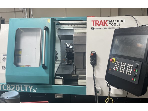
Trak Machine Tools has started offering a series of automation options on our TCsi series machines, one of them being an automatic door. With this procedure and drawings 36000-5 (TC820si Series), and 36000-6 (TC820LTYsi Series) the user will be able to complete the mechanical and electrical installation and alignment of the Automatic door option on the above series machines. The Programing and testing is covered in the Auto Door Programing Guide.
-
-
Before starting the Auto Door installation you need to verify the door is aligned and moving as smooth as possible. Start by checking the force required to open the door (break away torque) and move to the full open position (rolling torque). Check the force from full open to full close as well.
-
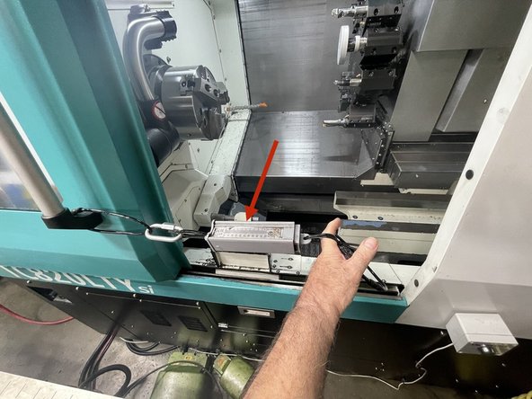
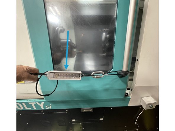
To measure the force to open and close the door we use a Fish Scale attached to the door.
-
The break away force to open the door (force to open the door out of the lock) should be 10-15 lbs, and the rolling torque (force from outside the door lock to full open) should be 3-10 lbs of force.
-
The break away force to close the door (force from full open) should be 10 to 15 lbs of force and the force to full close into the door lock should be 3 -10 lbs of force.
-
-
-
If the force to move the door is greater than the above values you need to realign the door to reduce the force required.
-
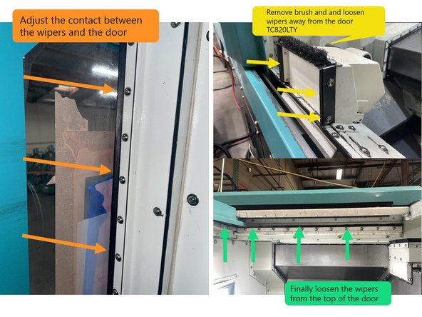
Start by loosening the door wipers on the front door and window. Loosen the wiper mounting screws and move the wipers away from the door to where they make a very light contact with the door.
-
Next remove the brush and adjust the wipers on the part catcher to make a very light contact with the door. Next loosen the wiper along the bottom of the door and adjust it to where it away makes a light contact with the door.
-
Then loosen the wipers along the top of the door and adjust them to where they make a light contact with the door.
-
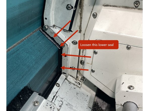
Finally loosen the lower door seal and adjust it to make a light contact as shown in photo 2.
-
Now with all of the wipers making little to no contact with the door, the door should move freely. If it doesn't go to the next step if it does go on to step 4.
-
-
-
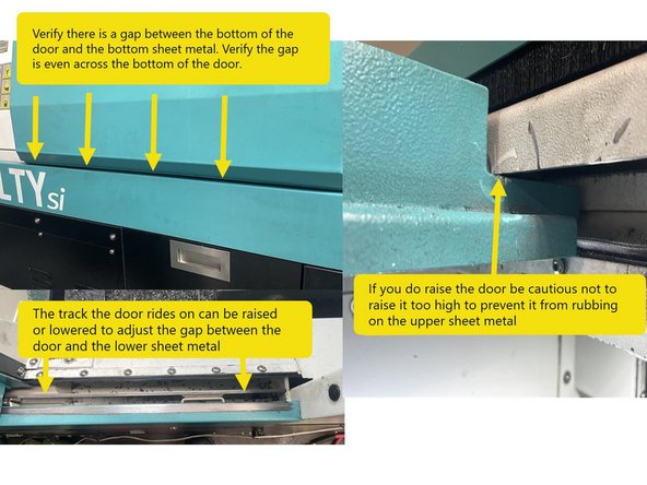
To check the door alignment, verify there is a gap between the bottom of the door and the lower sheet metal and that the gap is even across the bottom of the door. The steel track that the door rides on can be raised or lowered to adjust the height of the door off of the lower sheet metal.
-
If you do raise the door be careful not to raise it too high to prevent it from rubbing on the upper sheet metal. See Photo 1
-
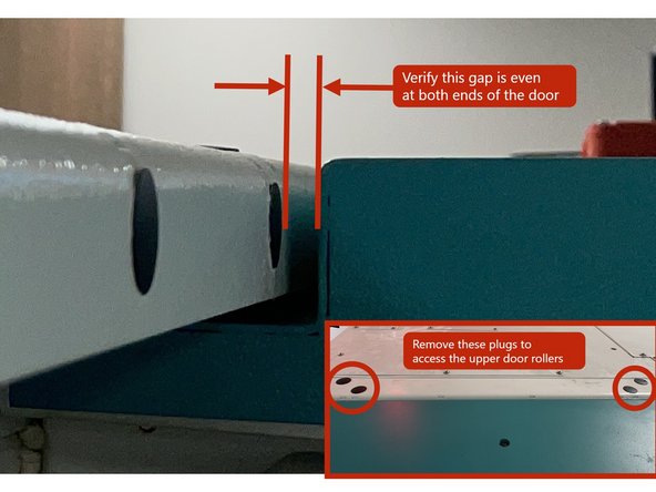
Next check the top of the door to the top sheet metal for a gap that is even across the door. See Photo 2
-
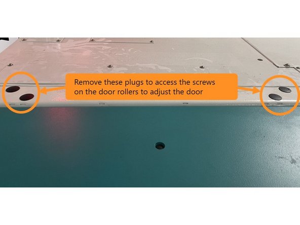
To adjust, open the door all the way and remove the black rubber plugs on the top sheet metal to access the screws for adjusting the upper door rollers. Loosen the rollers and adjust the door in or out to get an even gap and then tighten the rollers. See Photo 3
-
-
-
To start installing the Auto Door you need to drill the holes to mount the brackets for the Motor, the Yoke and the cable routing.
-
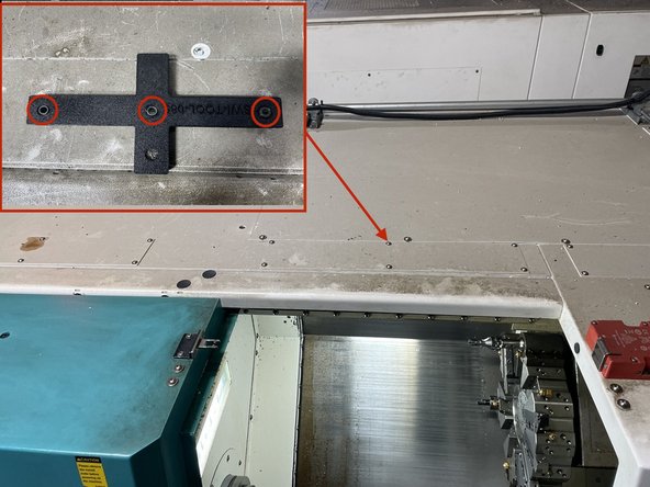
To drill the cable routing holes install the jig SWI-TOOL-085 as shown in image 1 using existing M5 holes and M5X20 screws that come with the jig.
-
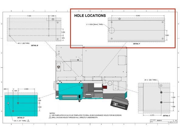
Drill the 28mm hole for the Home Switch and Motor cables into the electrical cabinet (Center Hole in Jig) and 2 holes for the cable tie holders (Outer 2 Holes in Jig). Drill using a 0.165" drill. Open up the center hole with a 25/64 drill to be able to use a Greenlee punch or similar device to cut the 28mm diameter hole.
-
To install the Home Switch Actuator and Belt Clamp Bracket, install SWI-TOOL-083 onto the door and drill the 3 holes through both the upper and lower sheet metal of the door. Then from the bottom side of the door open only the holes in the lower sheet metal to 0.500".
-
-
-
To install the Yoke and Motor you need to drill the holes to for the brackets that mount them.
-
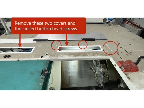
To locate the holes for the Yoke and Motor Mounting Brackets remove the top cable covers and circled button head screws as shown in photo 1.
-
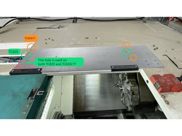
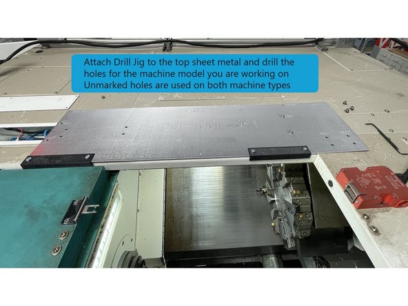
Then install jig SW-TOOL-084 using the holes marked in green for TC820 and orange for the TC820LTY. Use (4) of the cover mounting screws that were removed to mount the jig.
-
Drill the holes for the model machine you are working on. The 4 drill bushings not marked are used on both the TC820 and TC820LTY.
-
-
-
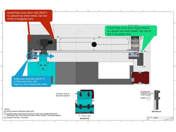
Once all of the holes have been drilled install the Plate-Auto Door-Left (36221) to the top machine sheet metal. Use 2 of the 3 nut plates (33311) to attach the plate to the top of the cabinet. See Image 1
-
Next install the Plate-Auto Door-Right (36222) to the top machine sheet metal. Use the 3rd nut plate (33311) to attach Plate-Auto Door-Right to the top of the cabinet. See Image 1
-
After both sub plates are installed Install the Yoke-Idler Pulley-Assembly-TC820 (36147-1) to the left auto door plate and adjust on the slots towards the motor. Snug the screws for now. See Image 1
-
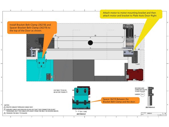
Attach the Gear Reduction to the Motor and then that assembly to the Motor Mounting Bracket. Then attach the bracket and motor assembly to the right auto door plate as shown in Image 2. Route cables from motor and switch through the cable way back to the electrical cabinet.
-
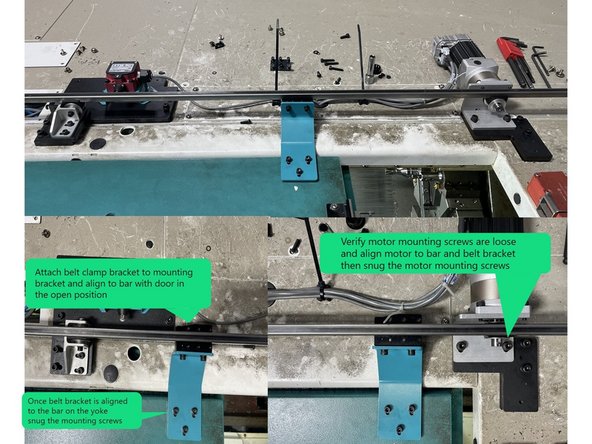
Finally install the Bracket-Belt-Clamp (36218) and Spacer-Bracket-Belt-Clamp (36219) to the door as shown in Image 2.
-
-
-
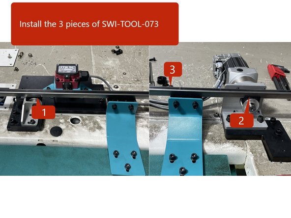
Use SWI-TOOL-073 and align the motor to the yoke and belt clamp.
-
Install the 2 pieces of SWI-TOOL-073 to the motor and yoke pulleys, and then install the alignment bar to the pulleys. See Photo 1
-
Next attach Clamp-Base-Belt (36142) to the belt clamp bracket and align with the SWI-TOOL-073 with the door all the way open and align to the yoke. Snug the belt clamp bracket mounting screws. Verify motor mounting screws are loose.
-
Now close the door and with the belt clamp still attached to the SWI-TOOL-073, and adjust the motor so that the pulley and the tool bar in the belt clamp are aligned. Reopen the door and check the alignment at that point. You may need to go back and forth a few times to get the motor and belt clamp aligned with the yoke.
-
Once the Motor, Yoke, and Belt Clamp are aligned tighten the mounting screws for the belt bracket, and motor. Then install the Plate-Belt-Clamp (33309) to the belt clamp bracket with (6) M4-0.7X16 25B SHCS.
-
-
-
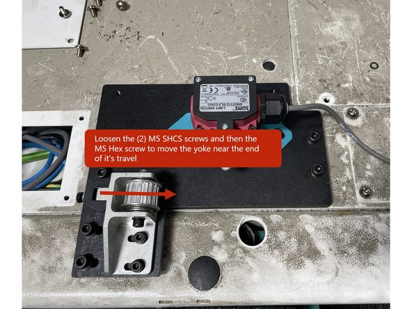
Cut the belt to 62in for TC820si and 66in for TC820LTYsi. Then loosen the M5 screws that attach the yoke to the mounting bracket and Loosen the M5 Hex screw and move the yoke to loosen it on the mounting bracket.
-
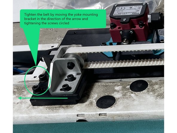
Install the belt around the top side of the pulleys and into the belt clamp and tighten the (6) M4 belt clamp screws. Tighten the belt by pulling on the yoke mounting bracket, then tighten the M6 screws.
-
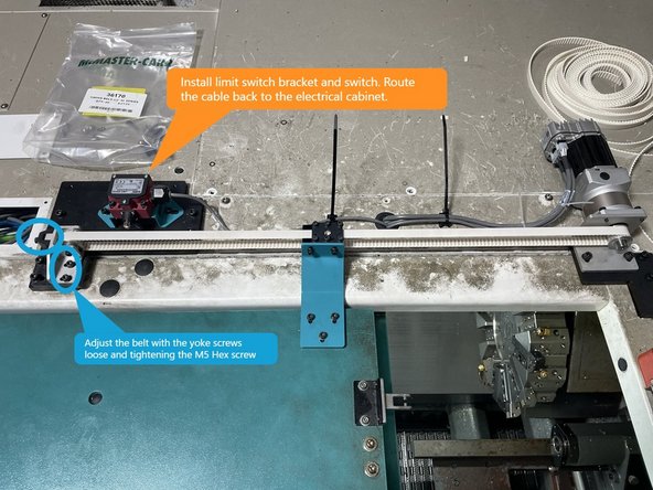
Open the door all the way and install Bando belt tension meter at the center of the belt travel. Adjust the tension to 50Hz +\- 3Hz with the (2) M5 socket head screws on the bracket loose and tightening the M5 hex head screw. If you cannot get the belt tension to 50Hz you may need to shorten the belt 1 or 2 teeth.
-
Install bracket-Limit Switch-Auto Front Door-VMC (36167) to the Plate-Auto Door-Left (36221). Then install Door Switch Assembly-Auto Front Door-Open-TC820 (22551-29) to it. Then route the cable back to the electrical cabinet.
-
-
-
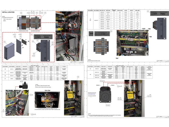
Using drawing 36000-5 wire up the Auto Door Option to the electrical cabinet.
-
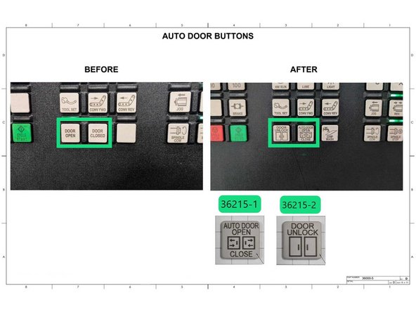
Once the wiring is complete change the Auto Door Buttons as shown in Photo 2. 36215-1 is Door Open/Close and 36215-2 is Door Unlock.
-
-
-
Now that the Auto Door has been wired up and is ready for operation it needs to be programed before it can be used. Use the link below to use the Auto Door Programming Guide.
-
Use this link to access the Auto Door Programming Guide: https://southwesternindustries.dozuki.co...
-
Once the Auto Door has been programmed you need to test it. Use the following test procedure to test the auto door.
-
Use this link for the Auto Door Test Procedure: https://southwesternindustriesinc.sharep...
-
-
-
Once the Auto Door has been programed and tested and is operating normally install the belt and motor covers to complete the procedure with the next few steps.
-
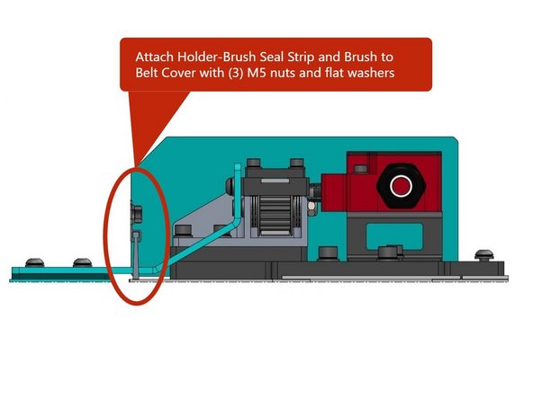
Install brush into Holder-Brush Seal Strip and attach the Holder-Brush Seal Strip and Brush to the Belt Cover using (3) M5 Hex nuts and flat washers.
-
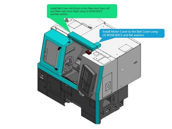
Install Belt Cover with Brush to the Plate-Auto Door Left and Plate-Auto Door Right using (3) M5X8 BHCS and flat washers.
-
Attach the Motor Cover to the Belt Cover with (3) M5X8 BHCS and flat washers.
-


Cancel: I did not complete this guide.
One other person completed this guide.