Introduction
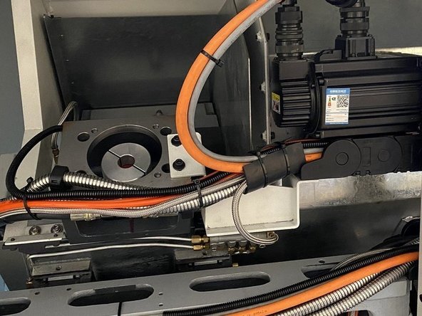
In this guide you will learn how to remove and replace the X Axis motor on the TC2 turning center. You will also learn how to adjust the X Axis home switch and set the index angle once the new motor has been installed.
-
-
Before starting the X Axis motor removal we need to remove the upper rear sheet metal panel to gain access to the X Axis motor and home switch.
-
Block off X Axis For Safety
-
The first thing that needs to be done before removing the X motor is the X Axis needs to be blocked off to prevent it from falling. The brake inside the motor is the only thing that prevents the X Axis from falling when the servo power is off. If the servo motor is removed from the ballscrew there is no brake to prevent it from falling.
-
-
-
With the X Axis blocked off E Stop machine to disable servos. Remove the motor and encoder cables and the (4) motor mounting screws.
-
Remove the motor from the X Axis ballscrew by separating it at the coupling. You may need to use a small screwdriver to assist in separating the coupling.
-
Once the motor has been removed, remove the half of the coupling that is attached to the motor shaft and reinstall it to the half on the end of the leadscrew. Be sure that one of the clamp screws in the coupling half you reinstalled is accessible with an Allen Wrench. Make sure to leave a 0.060" to 0.100" gap between the halves of the coupling.
-
-
-
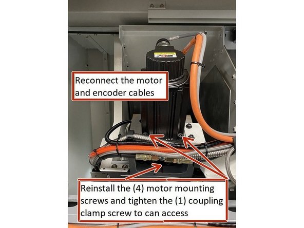
Install X Axis motor back into the motor coupling and reinstall the (4) mounting screws, and tighten them. Tighten the one coupling clamp screw you can access. Reconnect the motor and encoder cables to the motor.
-
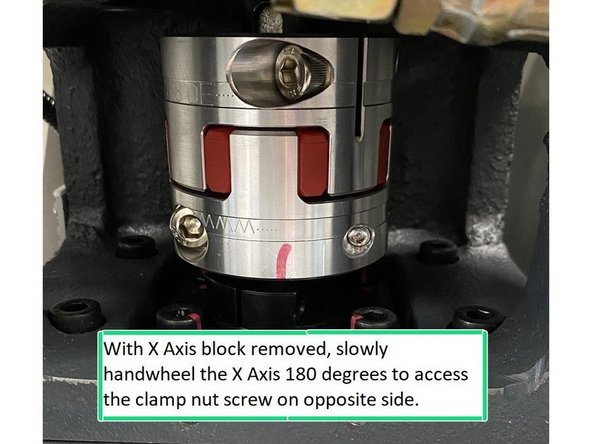
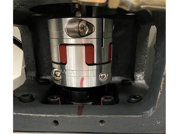
Enable the servos and enter service code 505, slowly jog off of the block on the X axis. Use the index angle display on the lower right of the screen to assist in slowly jogging the motor 180 degrees so that you can access the other clamp screw on the coupling to tighten it.
-
-
-
The home switch position comes adjusted from the factory and shouldn't need to be adjusted unless the switch has been readjusted or replaced. The following steps show how to verify the home switch position and adjust if necessary.
-
Note: With the exception of homing the machine, the following steps to adjust the home switch and index angle are all performed in service code 505.
-
Home the machine then open service code 505 and slowly jog the X axis to the upper hard stop. Mark the coupling and casting and then slowly jog the X Axis away from the hard stop one full revolution. Your marks should line up. Now jog the axis another 180 degrees off of the hard stop this is where the home should be set.
-
You can use the index angle display to track the ballscrew rotation from the hard stop.
-
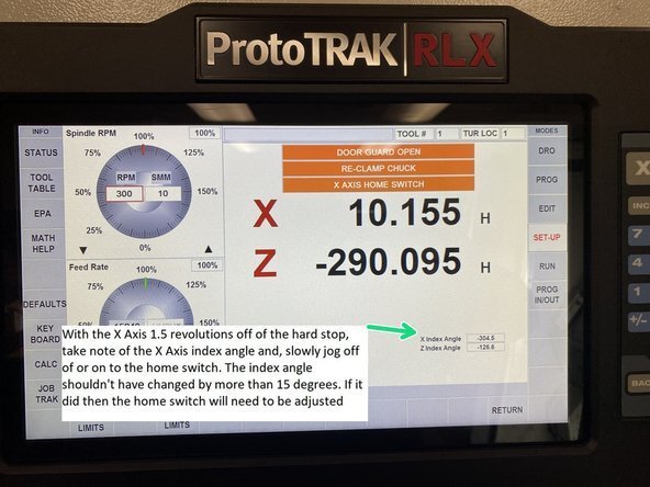
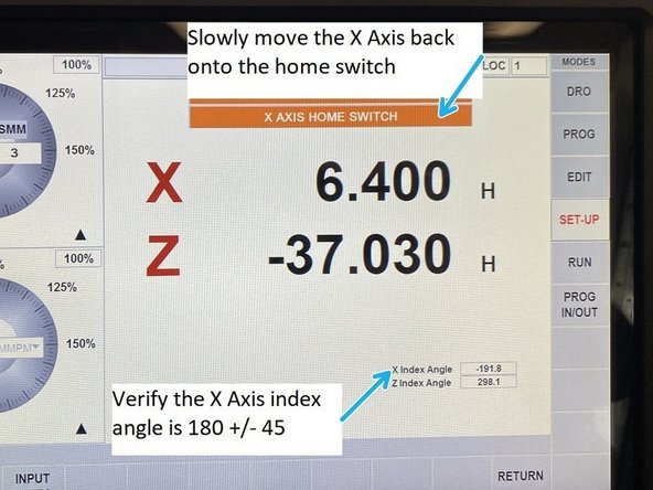
To verify the home switch location if the home switch is tripped, take note of the index angle and slowly jog the X Axis off of the home switch until the home banner goes out. Check the index angle it shouldn't have changed by more than 15 degrees. If it has the home switch needs to be adjusted.
-
To verify the home switch location if the switch isn't tripped, again take note of the index angle and slowly jog the axis on to the home switch until the home banner is displayed on the DRO. Again check the index angle, it shouldn't have changed by more than 15 degrees. If it has the home switch needs to be adjusted.
-
If the home switch doesn't turn on or off at 1.5 revolutions +/- 15 degrees off of the hard stop then the home switch will need to be adjusted.
-
-
-
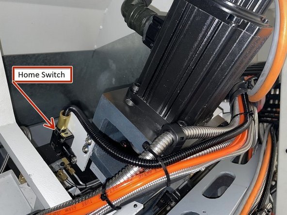
The home switch is mounted on the left side of the X motor casting when viewed from the rear of the machine.
-
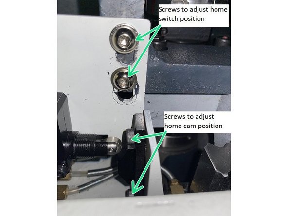
To set the home switch, move the X Axis back to 1.5 revolutions off of the hard stop, then loosen the screws on the home cam and adjust it so that the home switch just trips. If there isn't enough adjustment on the home cam you can loosen the home switch bracket screws and adjust using the switch bracket.
-
Make sure that when adjusting the home switch the cam is on the bottom side of the switch actuator, if not home will be in the wrong location and there will be a loss of travel in the X Axis.
-
To verify that the home switch is set correctly, take note of the current index angle, and then slowly jog the X axis off of the home switch and then back onto it. The change in the index angle shouldn't be more than 15 degrees. If it is you need to realign the switch or cam.
-
-
-
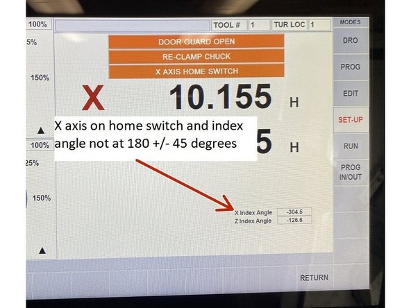
To adjust the index angle, home the machine and enter service code 505. Move the X axis up slowly until the X Home switch banner is illuminated. Check the index angle , if it isn't 180 +/- 45 it needs to be adjusted.
-
Do not disable the servos
-
Block off the X axis so it remains on the home switch. Remove the motor mounting screws, separate the coupling and remove the motor. With the motor removed but still connected, slowly handwheel the motor to 180 degrees on the index angle display in service code 505. Remove the coupling from the motor and reinstall on the other half in the machine.
-
When reinstalling the coupling be sure that one of the clamp screws is accessible so when the motor is installed it can be tightened.
-
Reinstall the motor and tighten the one clamp screw you have access to on the coupling. Now slowly jog the X axis off of the block and move 180 degrees so you can tighten the other clamp screw.
-
Rehome the machine. Go back into service code 505 and slowly jog the X axis into the home switch and check the index angle. It should be 180 +/- 45 if not repeat the above steps and check again. Once the index angle is in spec reinstall the rear cover and return machine to production.
-


