-
-
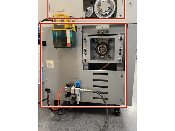
To prep for replacing the spindle motor start by removing all the necessary sheet metal to gain access to the motor.
-
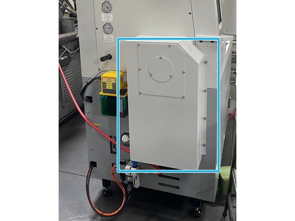
Remove the motor cover on the left side of the machine.
-
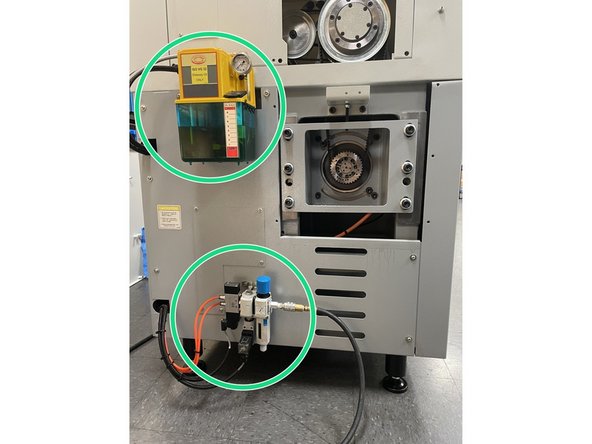
Remove the lube pump and the Air regulator/ solenoid assembly. Set the lube pump on a bucket or something tall enough to keep it from hanging on the oil line or electrical cable.
-
Remove the upper and lower left side covers.
-
-
-
Remove the spindle motor access cover from the lower front sheet metal cover on the machine. This will give you access to the motor terminal box so you can disconnect the wiring from the spindle motor.
-
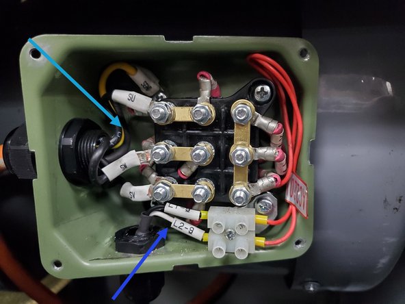
Open the terminal box on the motor, remove the plastic cover over the wires and take note of the wire positions.
-
Disconnect wires L1-9 and L2-9 from the 2 pin terminal block .
-
Next remove the motor wires SU, SW, SV and SGND from terminal blocks Z, X, Y and ground on the motor respectively. Remove the lock nut from the cable strain relief and remove the lock nut and cable from the junction box.
-
-
-
This step pertains only to machines equipped with a hydraulic chuck. If you have a manual chuck skip to step 4
-
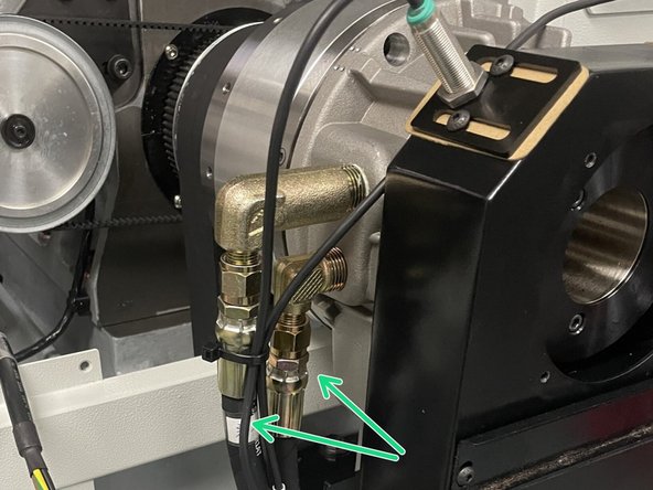
Before removing the hydraulic lines check to see if they are labeled as to where they go. If not label them before you remove them so they can be put back in the right location.
-
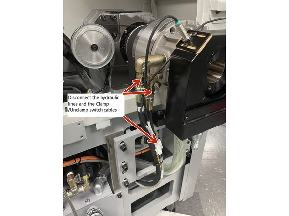
For machines equipped with the optional hydraulic chuck Disconnect the hydraulic lines.
-
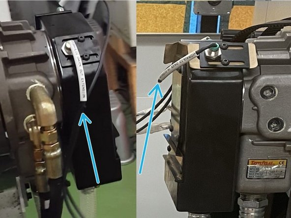
Disconnect the Clamp and Unclamp switch cables.
-
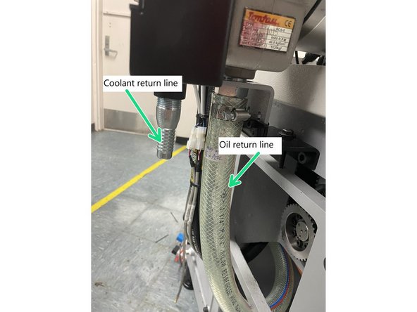
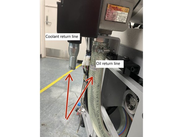
Disconnect the oil and coolant return lines.
-
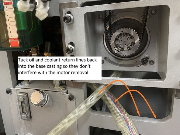
Tuck oil and coolant return lines back into the base casting so they don't interfere with the motor removal
-
-
-
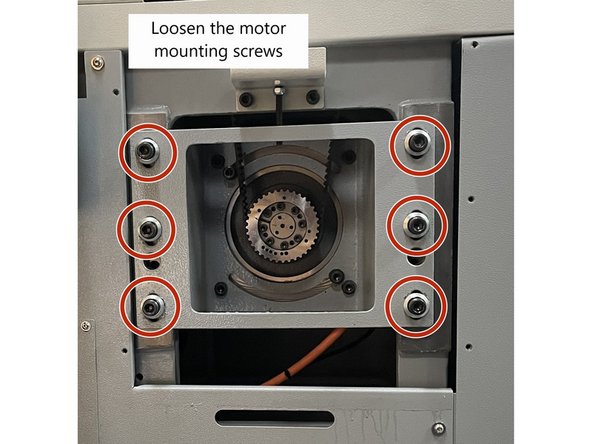
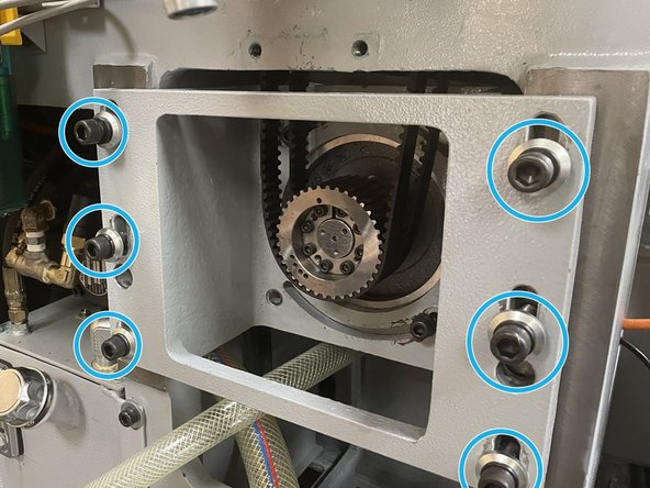
Loosen the six(6) motor mounting screws.
-
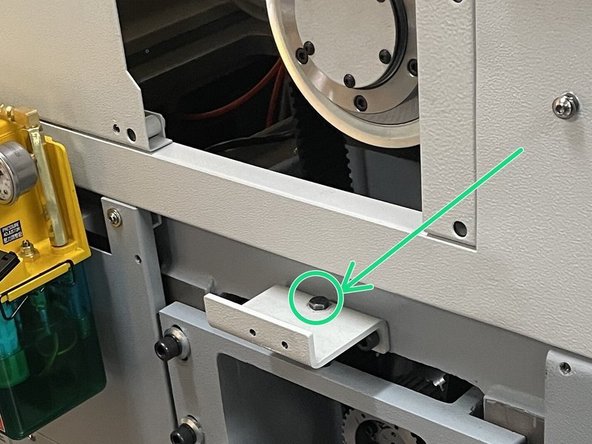
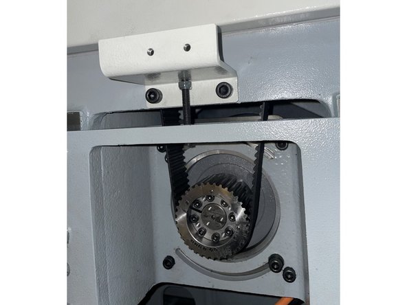
Using the push pull motor adjuster, tighten the screw to adjust the motor up to loosen the drive belts and then remove them.
-
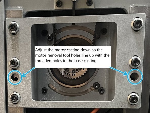
Once the belts are removed adjust the motor down until the two(2) threaded holes in the base casting line up with the through holes in the motor casting for the motor removal rods.
-
-
-
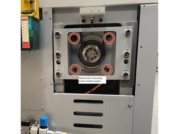
Remove the four(4) screws that mount the motor to the motor mount casting. Circled in green.
-
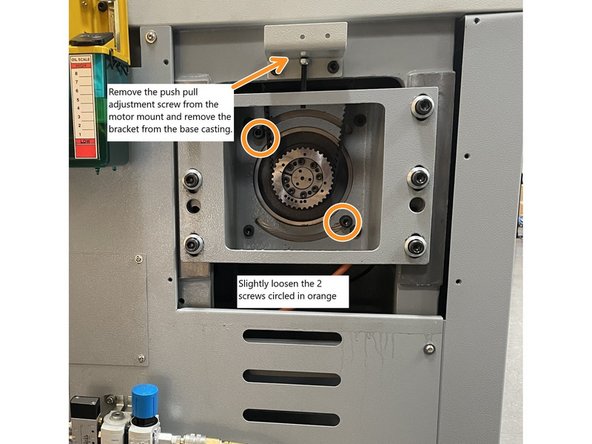
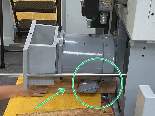
Crack Loose the two(2) motor mounting screws that allow for rotational adjustment of the motor on the motor mounting bracket. (Circled in orange). Rotate the motor so that the electrical box is facing downward. Snug up the screws. Remove the push pull adjustment screw from the motor mount and then remove the push/pull bracket from the base casting.
-
Caution motor is very heavy only loosen the screws circled in orange. Removal will cause the motor to fall which could cause damage or injury.
-
Insure the lower left side sheet metal cover is removed before attempting to remove the motor. Photo shown prior to cover removal
-
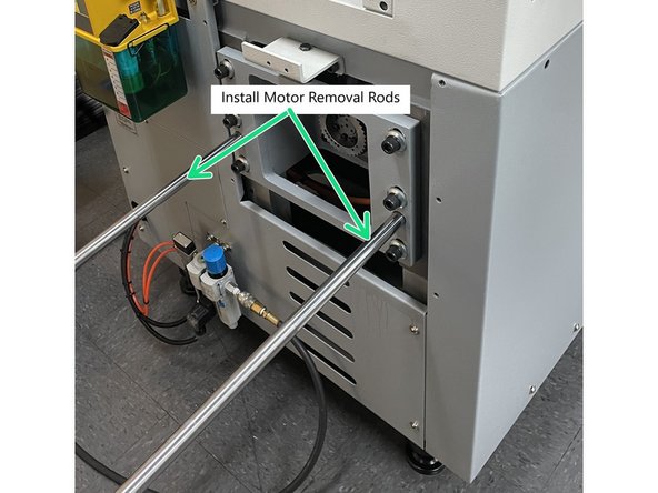
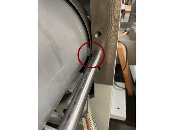
Verify the holes in the motor casting are aligned with threaded holes in the base casting, then install the motor removal rods. Thread them all the way in until they stop. Remove the six(6) screws that attach the motor casting to the base casting.
-
-
-
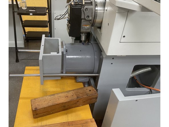
Slowly pull the motor out on the removal rods. Keep an eye on the electrical box, you may need to rotate the motor slightly to get it to clear the casting. You may also need to rotate the motor to clear the screw heads on the motor end cover.
-
Use a height adjustable cart or some other lifting device to support the motor once it is out of the casting.
-
Caution: motor is heavy, use caution when removing.
-
Once the motor is supported remove it from the motor removal bars.
-
-
-
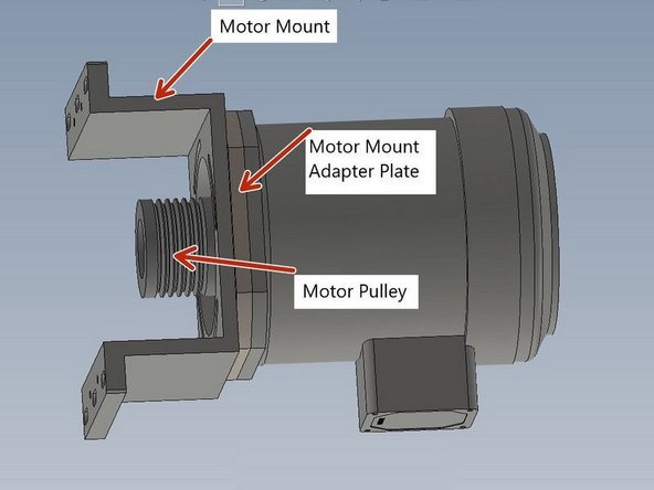
Once the old motor has been removed, remove the motor mount, motor adapter plate and pulley and install them on the new motor. Install the motor mount to the motor using only the 2 rotational screws at this time. When installing the pulley align it so that the taper lock is flush with the motor shaft.
-
With the mounting bracket, adapter plate and pulley installed on the new motor, put it onto the lifting device used to remove it and position the motor back onto the installation and removal bars.
-
You may need to put a 4X4 under the back of the motor between the lifting device and the machine base casting to raise it up high enough for the electrical box on the motor to slide back into the casting. You may also need to rotate the motor so the electrical box and screw heads on the rear cover clear the casting.
-
Slide motor into casting and install the six(6) mounting screws. Remove the motor installation and removal rods. Leave mounting screws slightly loose at this time.
-
-
-
Reinstall the belt adjustment bracket and raise the motor up so the belts can be installed.
-
Next rotate the motor so the electrical box is aligned with the opening in the front of the base casting and install the four(4) screws that attach the motor to the motor mount. Then tighten them and the two(2) screws that hold the motor for rotational purposes.
-
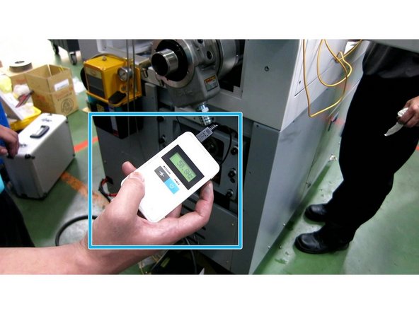
Using a digital belt tension meter adjust the belt tension to 48Hz +/- 2 Hz. Then tighten the six(6) motor mount bolts.
-
-
-
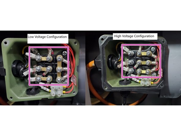
Before installing the wires to the motor verify that the motor is jumpered correctly. See Photo 1
-
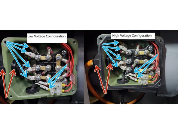
Reinstall cable and strain relief into the terminal box and reinstall the lock nut and tighten. See Photo 2
-
Next reinstall the motor wires SU, SW, SV and SGND to terminal blocks Z, X, Y and ground on the motor respectively. Reconnect wires L1-9 and L2-9 to the 2 pin terminal block . See Photo 2
-
Next reinstall the plastic cover over the wires and close up the terminal box. See Photo 3
-
Once the wires have been connected and the wire cover is replaced on the spindle motor terminal box, reinstall the spindle motor access cover to the lower front sheet metal cover on the machine. See Photo 3
-
-
-
For machines with manual chucks skip this step and move on to step 11.
-
Reinstall the oil and coolant return lines.
-
Reinstall the Hydraulic lines.
-
Reconnect the hydraulic chuck open and close sensors.
-
-
-
Reinstall the upper and lower left side sheet metal covers.
-
Reinstall the lube pump and the air regulator assembly.
-
Finally reinstall the motor cover.
-
-
-
Once the spindle motor has been replaced and every thing has been put back normal operating conditions the new motor needs to be calibrated and tested. Go to service code 510 and select Spindle Calibration and then start. This will run the calibration routine, it will take about one(1) minute.
-
Once the spindle calibration has been completed the spindle motor should be tested. Run the spindle starting at 150 RPM's high speed option and 50 RPM"s for high torque for about a minute, then increase in 500 RPM increments until you reach max speed. Look for any faulting or abnormal noises.
-
Next start at zero and accelerate from zero to max speed (2500 on high torque machines and 4000 on high speed machines) Spindle should reach full speed in 4 seconds. Next stop spindle it should reach zero RPM's in 4 seconds. Next from max speed E-Stop machine spindle should stop in 4 seconds.
-
Do the above checks a few times while also checking for any faults or abnormal noises. If all checks out verify all of the covers and parts have been reinstalled and return the machine to production.
-
Almost done!
Finish Line


