Tools
Parts
No parts specified.
-
-
Insert USB firewire cable into axis drive to be tested. Plug other end into Delta RJ45 adapter and then plug adapter into USB port on laptop.
-
Open ASDA software on laptop, select device ASDA-B2 and select OK. Click on red OFFLINE tab, it should change to say ONLINE in green.
-
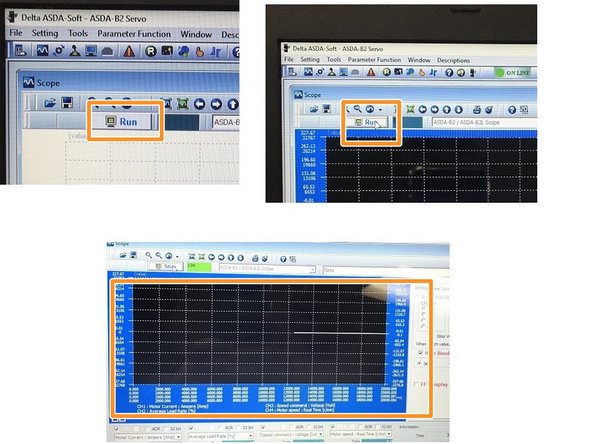
Click on scope icon, you should then see a scope graph on the display.
-
-
-
For channel 1 select Motor Current AMP. For Channel 2 select Average Load Rate %. For channel 3 select Speed Command Voltage. For channel 4 select Motor Speed Real Time.
-
Select PROG IN/OUT on pendant. Open the ProtoTRAK folder, select the SWI PT10 TEST PROGRAMS folder. Select program for correct machine type and axis. Select yes when control asks to overwrite current program.
-
Machine will travel full stroke in the axis that is selected at full speed. Make sure that the table, saddle or ram is at the edge of travel in opposite direction of test to prevent crash.
-
Once axis to be tested is in position, zero out control.
-
Make sure Z-axis is at a safe height to avoid crash.
-
-
-
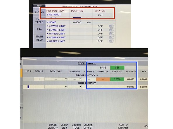
Select SETUP, then select REF POSN. Hit INC SET to set Z retract.
-
Select TOOL TABLE from the INFO key selection on left of screen. Hit INC SET to set base tool and continue to hit INC SET to set tool 1 to 0.0000 Z offset.
-
Select Run on scope, you will then see a line appear on the right side of the screen moving left.
-
Press GO on the pendant, press FWD to turn spindle on, press GO one last time to start test program.
-
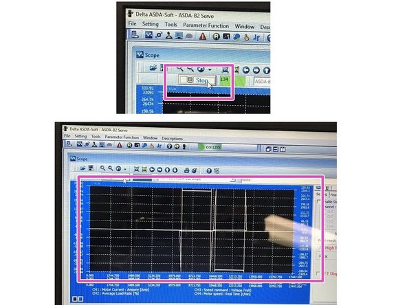
Press stop on scope once the plot is in the center of the scope. You will then see the amperage plot on the screen.
-
-
-
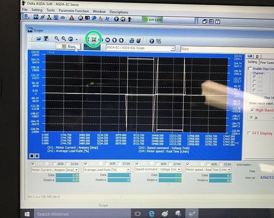
Select fit to screen button to fit plot peaks onto screen.
-
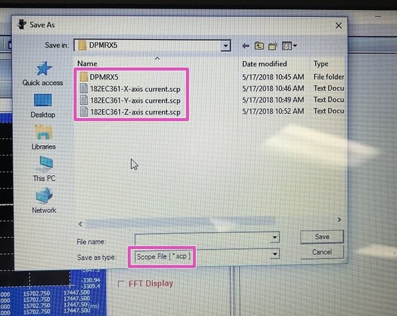
Save file to storage device as a .scp file, this way the file can be viewed and edited by engineering if needed.
-


