Introduction
This is a generic specification for the Spindle Bearing Run-In procedure for any TRAK Lathe that has tapered roller bearings. Results of this procedure will give the technician an idea of the proper headstock temperature at various RPMs as well as oil flow volume.
Note: The end of this guide has sample data for various lathes.
TRAK 1630 HS RX/SX lathe has a cartridge type spindle and requires a different test procedure. ES 427 is the internal TRAK reference material for the 1630HS.
Original Release ECN 13855 6/13/12 By: TO
-
-
Important! – Before you begin bearing run-in procedure, make sure that the spindle bearings are installed properly, i.e. the spindle rolling torque is within specified range, and without a noticeably high breakaway torque.
-
Secondly, make sure that the bearings are getting proper lubrication.
-
-
-
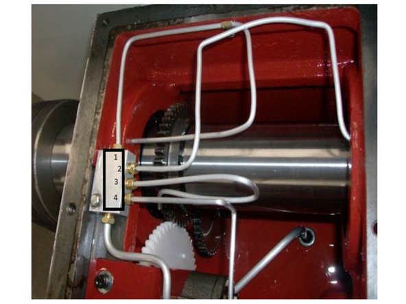
See photos for typical temperature checking techniques.
-
Use an Infrared (IR) type thermometer to measure and record the ambient temperature of the headstock casting which is the data needed to verify proper run-in.
-
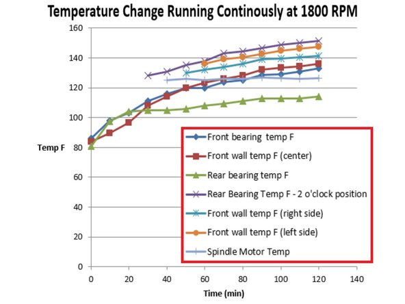
Ambient temp reading must be done before running the spindle. This data is used for the base of the max range of temperature change. If the lathe increases more than 50° F during the testing, there could be oil flow problem (see specifics for each lathe, 30120 has a higher temp allowed).
-
-
-
Warning! If the temperatures does not stabilize, or at any time reaches ~140° F, Stop the spindle immediately and let it cool off until temperatures drop below 120° F, then start the process over again.
-
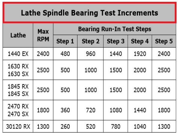
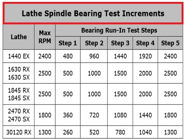
Start the spindle at the first step for your specific lathe. After about 5 minutes of running, measure and record temperatures near the outer race area of the front and rear tapered roller bearings. Check the temperatures about every 5-10 minutes until you see that the temperatures does not increase, or start to decrease.
-
When the first step is stable, proceed with the second and the rest of the steps. Once the temperatures stabilize at the last testing step, the spindle bearing run–in process is complete. The total process takes about 4-6 hrs. on average (1-1½ hr per RPM step).
-
If the temp does not stabilize, perform the following checks:
-
Check and make sure that the oil lubrication is functioning properly.
-
If the lubrication is working, check and make sure the bearings are installed properly. Look at the outer race for any abnormal or uneven wear patterns, or discoloration.
-
If bearings are installed correctly, check if the bearings are defective, outer race runout, etc.
-
If the lathe fails the test, proceed to the next step to check oil flow. Correct any oiling problems and restart the complete five step test rechecking each step for temperature.
-
-
-
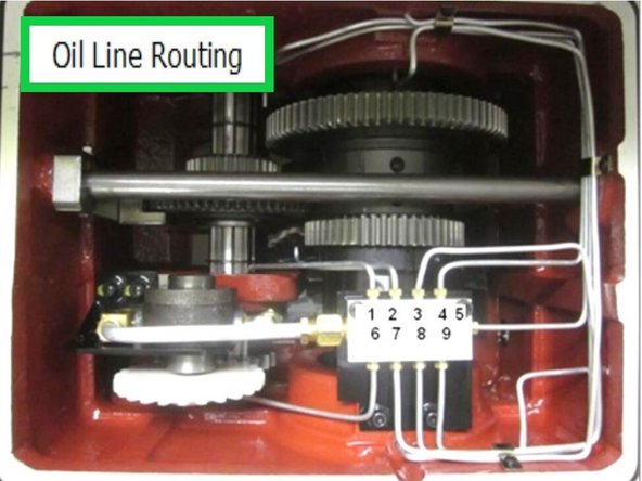
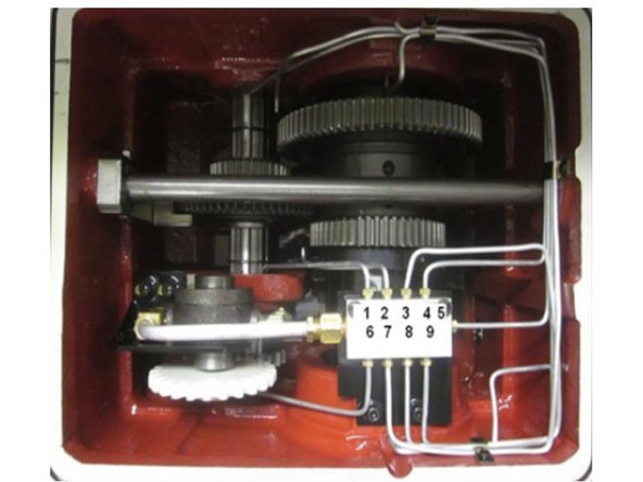
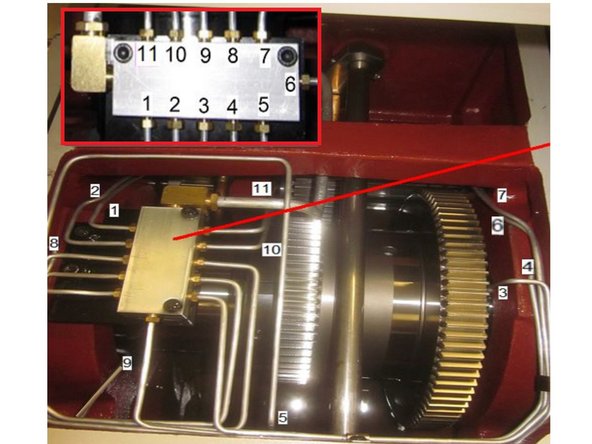
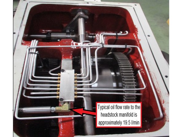
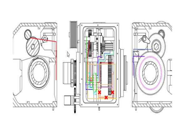
Make sure the bearings are receiving proper amount of lubrication (oil flow). See Photo for a typical 1845 headstock lubrication layout and line routing.
-
Information in this step is for the 1845, check the steps below for photos and tables showing the specific details for your lathe.
-
To check the oil flow rate reaching the Front and the Rear spindle bearings, follow the procedure as outlined below:
-
Remove the headstock top cover, and replace it with a clear sheet of polycarbonate of a similar size so you can see the oil flow inside the head as it is running.
-
Start the spindle at the first step RPM and make sure that the oil pump starts pumping oil to both front and rear spindle bearings, as well as to all other lubrication areas.
-
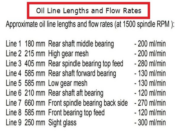
Once the oil starts to flow, turn the spindle off and slightly pull out the rear oil line #3, and the front bearing oil lines, #7, and #8. Check the schematic for your specific lathe to find the matching oil lines mentioned here.
-
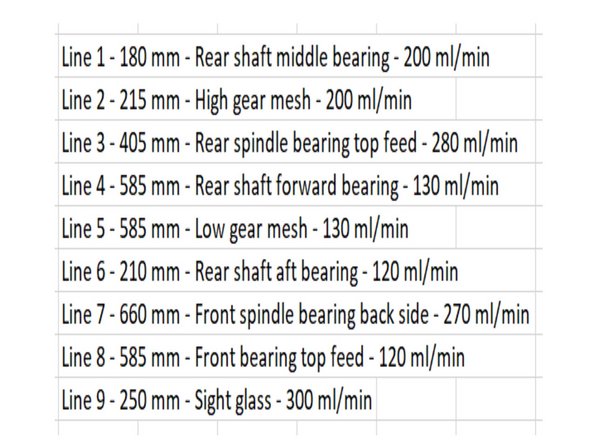
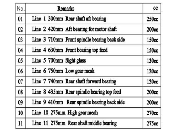
TRAK 1845 Lathe Oil Specifications to use as an example of what readings to expect from an 1845.
-
-
-
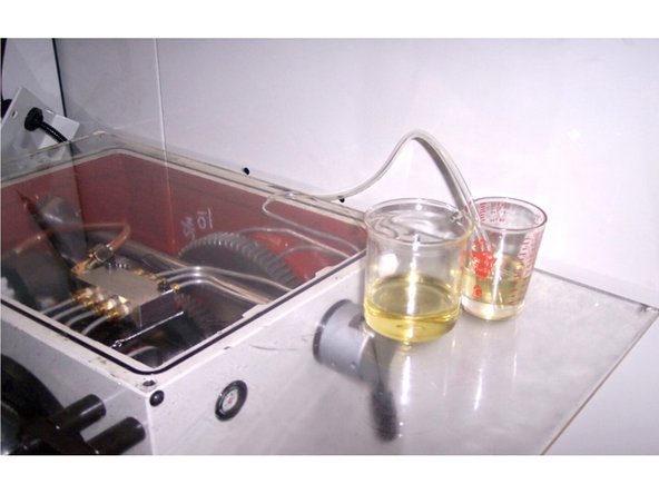
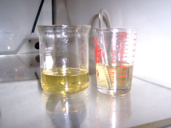
Prepare a stopwatch, a measuring cup (with milliliters graduation and around 500 ml capacity), a second non-graduated cup, with a little larger capacity than the measuring cup, plus a piece of clear flexible 4 mm ID (6 mm ID for larger lathes) tubing about 12 inches (300mm) long, see photos.
-
Slide one end of the flexible tubing over the oil line that lubricates the front spindle bearing. Temporarily place the other end of the flexible tubing inside the non-graduated cup to catch any oil from dripping out.
-
Cover the headstock top with the clear plastic cover to keep the oil from splashing outside of the headstock when spindle starts to rotate. Start the spindle at step 3 RPM and wait until the oil starts to uniformly flow out of the flexible tube, then move the end of the tubing inside the measuring cup and start the stopwatch.
-
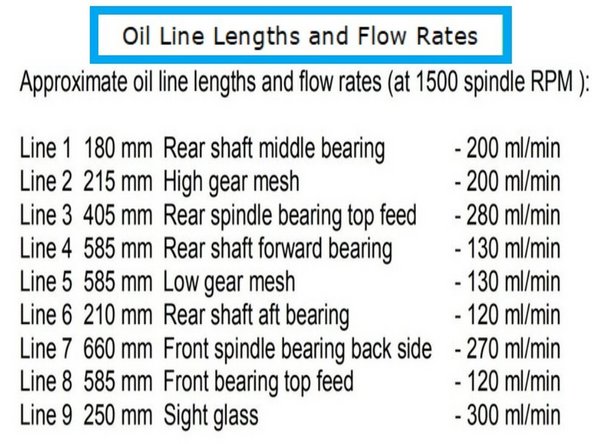
Measure the amount of oil that flows into the cup in 15 seconds, then multiply the results x4. See tables for your machine type to determine the correct oil flow for the line that is being measured.
-
After the sufficient oil flow is verified, disconnect the oil flow test tubing, readjust the oil lines back to normal, and re-install the headstock top cover.
-
-
-
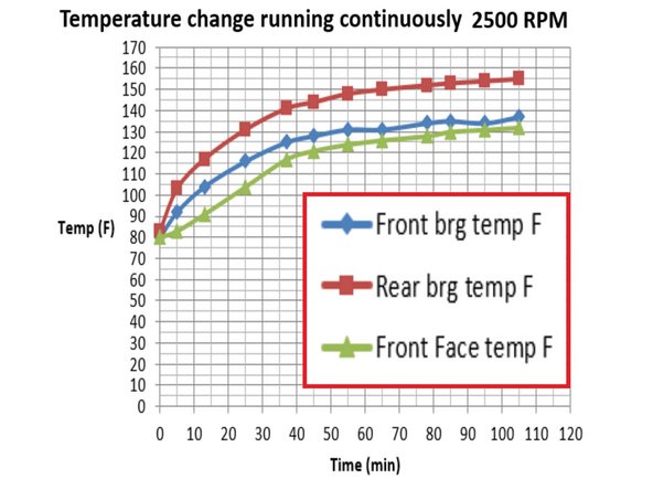
Five minute warm up at 500 RPM. Testing at 2500 RPM.
-
Initial Temperatures:
-
Front Bearing 80°
-
Rear Bearing 82°
-
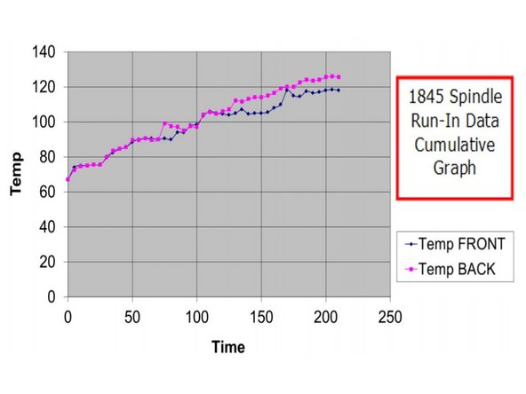
Front bearing 30 min temp change from graph - 40°
-
Rear bearing 30 min temp change from graph - 55°
-
Approximate saturation point - 157°
-
Oil flow rates (ISO VG32) (SAE 10W oil equivalent). Front Bearing - 400 ml/min @2500 RPM. Rear bearing - 400 ml/min @2500 RPM.
-
-
-
Oil Lines and flow rate at 2500 RPM:
-
Line 1: 16" rear spindle bearing 540 mil/min
-
Line 2: 16" front spindle bearing 600 mil/min
-
Line 3: 9" gears 800 mil/min
-
Line 4: 11" site glass 520 mil/min
-
-
-
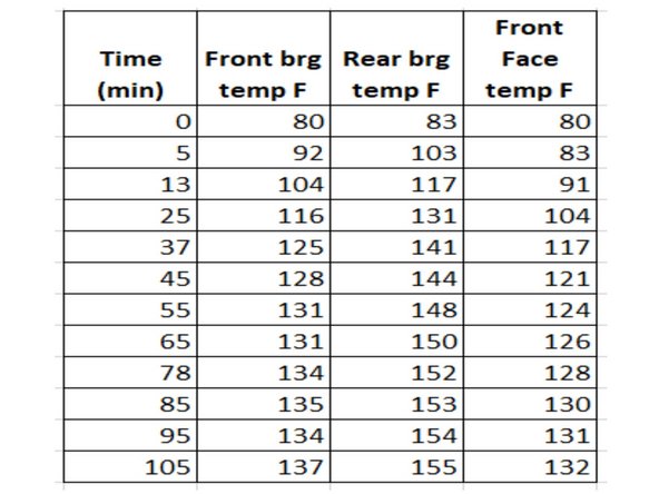
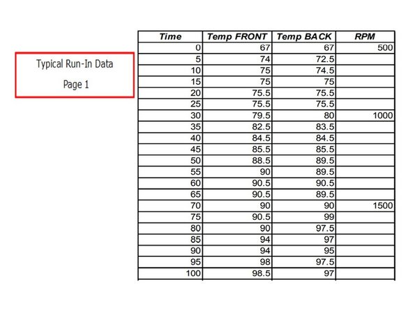
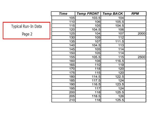
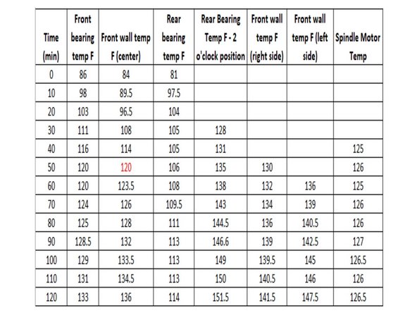
Typical test data to use as a reference, this example is a 1845 RX lathe with a max speed of 2500 RPM. Proper testing requires 5 tests at different speeds.
-
The operating temperature is the important data for all lathes. This guide provides examples from our 1845 RX lathe as a reference.
-
-
-
The front bearing should receive around 120 ml/min from the top line #7, and around 270 ml/min from the side line #8. The rear bearing should receive around 280 ml/min from line #3. Sample data shown is from 1845 RX.” to “See tables for your machine type to determine the correct oil flow for the line that is being measured.
-
Note: The maximum oil flow rate (at step 3 RPM) to the rear bearing (in line #3), should not exceed 330 ml/min. Also, the combined flow (in lines #7 and #8) to the front bearing should not exceed 450 ml/min.
-
-
-
Ten minute warm up time at 500 RPM, lathe initial temp 84° ambient air temp 73°.
-
Breakaway torque when hot after continuous test - 40 in-lbs and 30 to 35 rolling torque, breakaway and rolling torque after it cooled down - 25 and 20 respectively and very smooth
-
-
-
Insert wisdom here.
-
-
-
By: T.O, P.B. Rev. 11-8-19
-
Experience shows that after 45 - 60 minutes of operation at 1,300 RPM, headstock temperatures are 140° F and may still tend to rise. This is acceptable. Important to have good oil flow. Minimum flow is > 750 cc/min on the front and rear bearings on 3 lines. Unlikely 30120 will be operated at 1,300 RPM for long periods of time.
-
-
-
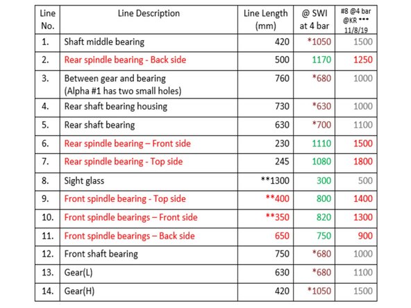
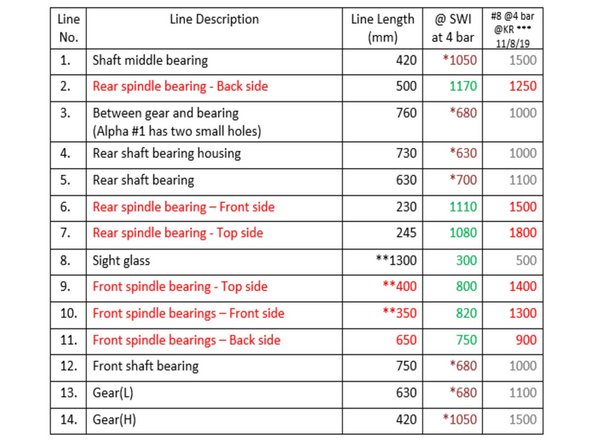
Measured at SWI, @ 4 bar pump pressure, machine serial #4.
-
Measurements in red are the critical flows to the front and rear spindle bearings, the minimum flows on each line must be > 750 cc/min.
-
* - These flow rates were not actually measured, but were derived and based on ratios of actual KR and SWI measurements at 2.5 bar. These flows will need to be measured once KR tube bending and cutting is more consistent, and spindle bearings flow rates repeat reasonably closely on several consecutive machines.
-
** - These line lengths were changed from the original KR dwg. to provide better lubrication to the front spindle bearing – stared on machine #2.
-
*** - These measurements were taken on machine #8 at KR (@4 bar pressure), received in emails on 11/8/19 and 11/12/19.
-


