-
-
Verify all electrical connections:
-
Extension Cable to Computer
-
Work Lights to Extension Cable
-
If all connections are present and Lamp still does not function, proceed to step 2 below.
-
-
-
Unplug Extension Cable from the Computer Module and the Work Light cables.
-
Verify there is continuity between Pin 1 P1 (red wire) to Pin 1 P2 and P3. Then verify continuity between Pin 2 P1 (black wire) to Pin 2 P2 and P3 (see connectivity chart on drawing)
-
Note: Set meter to continuity and verify 'beep' and zero ohms (0) on screen.
-
If Cable continuity fails test, replace Extension Cable, P/N 27635-50.
-
If Cable continuity passes test, proceed to step 3 below.
-
-
-
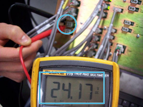
Locate the "Out-Lights" connector on the Computer Module, near lower left corner.
-
Set meter to DC Volts and verify 24 Volts between pins 1 and 2 on connector.
-
If 24 Volts is present and the Extension Cable passes the continuity test in step 2, replace the entire Lamp Assembly, P/N 29066.
-
Almost done!
Finish Line


