Introduction
This upgrade replaces the original Air Cylinder Kit used on VMC and TMC machines.
The original design was prone to coming loose over time. This new kit addresses that issue with a more secure assembly.
This guide provides step-by-step instructions for removing the old components and installing the improved kit.
-
-
Before installing the upgraded Air Cylinder Kit, remove the current assembly.
-
Before starting disconnect the air from the machine.
-
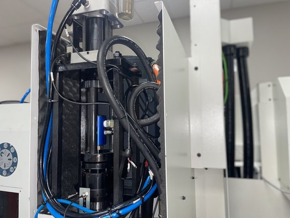
Remove the front cover from the headstock. (Photo 1).
-
After cover removal, determine if the machine is:
-
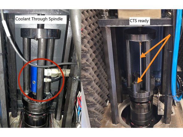
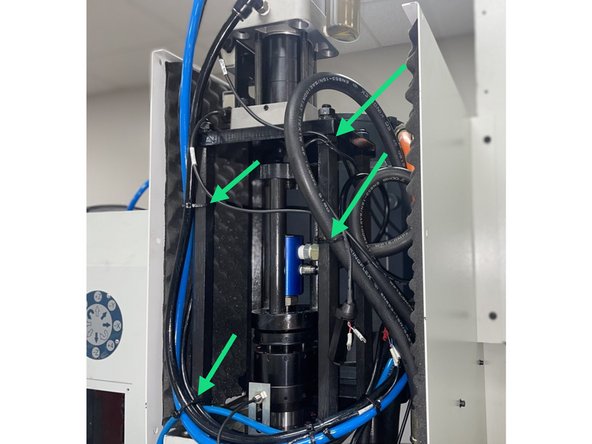
Coolant Through Spindle (CTS) Equipped: Has a rotary joint with coolant and air lines (green arrow – Photo 2).
-
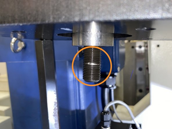
Coolant Through Spindle (CTS) Ready: No rotary joint; only an air blast line attached to a threaded rod and running through a support brace into the spindle (blue arrows – Photo 2).
-
-
-
For CTS machines: Disconnect the coolant hose and air line, then remove the fittings from the rotary joint.
-
For CTS Ready machines: Remove the lower support bracket and air line together, being careful not to bend the air line.
-
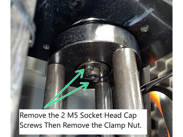
Remove socket head screws securing the clamp nut to the upper plate. Unscrew and remove the clamp nut (left-hand thread).(Photo 2)
-
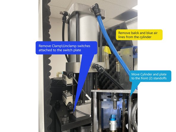
Remove the blue and black air lines from the Clamp\Unclamp cylinder.
-
Remove Clamp\Unclamp Switches attached to the switch plate to be able move the Cylinder and mounting plate to the front (2) standoffs.
-
Remove the (4) mounting nuts from the cylinder plate. Shift the plate to the two front standoffs so it hangs outside the frame.
-
Cut any cable ties as needed to move the cylinder and plate. You may need to remove the Clamp/Unclamp switch plate with switches attached to be able to move the cylinder and plate. (Photo 3).
-
-
-
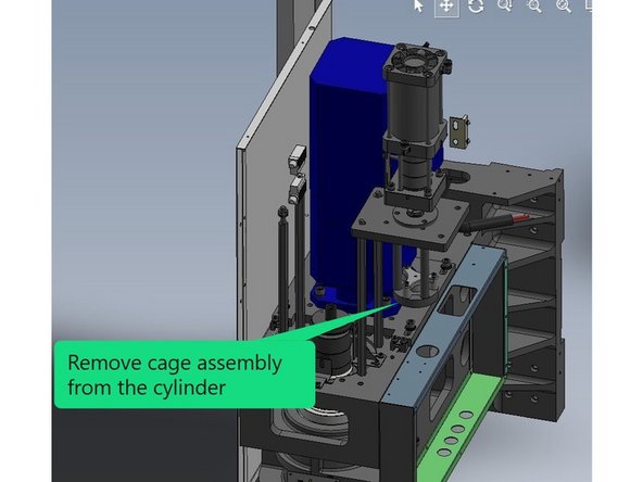
Unscrew and remove the cage from the air cylinder (left-hand thread).
-
Inspect the threaded rod for damage; replace with P/N 3202041090 if needed.
-
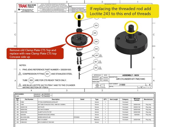
If replacing the threaded rod, apply Blue Loctite 243 to the end that threads into the clamp/unclamp cylinder (left-hand thread) then reinstall clamp nut and tighten. See Yellow Balloon in Photo 3.
-
Remove the old "Clamp Plate CTS Top" from the cage assembly and install the new Clamp Plate (P/N 3263041060) Concave side up. See Drawing 31889 in Photo 3.
-
-
-
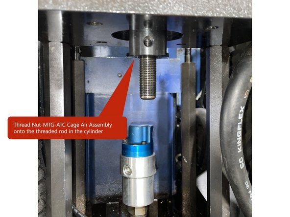
Thread the Nut Air Cylinder (P/N 3263041050-1) onto the threaded rod in the cylinder (left hand thread) convex side down. Thread it far enough to allow installation of the Clamp Plate-CTS-Top (3263041060), Wave Disk Spring Washer (50240308), and Clamp Nut (3202041100-1).
-
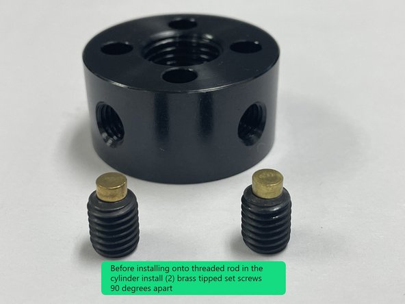
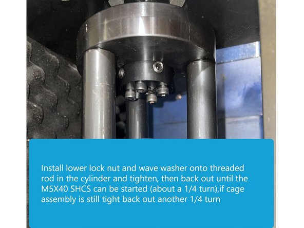
Before installing the lower clamp nut and spring washer onto the threaded rod in the cylinder install 2 brass tipped set screws into the nut 90 degrees apart.
-
Install cage assembly to threaded rod then install clamp nut with spring washer.
-
Next Install one M5-0.8x40 SHCS through the Clamp Nut and into the Clamp Plate-CTS-Top on the threaded rod and tighten lower lock nut until tight, then back off until the M5 SHCS can thread into the upper clamp nut, (about a 1/4 turn), if the Clamp Plate-CTS-Top assembly is still tight back off another 1/4 turn and thread into the upper clamp nut.
-
There should still be a slight pivoting motion between the clamp plate and lock nuts for self-alignment. You want the cage assembly to be able to move under the tension of the wave washer but you don't it to be sloppy loose.
-
Install the remaining 3 screws and leave them slightly loose for now.
-
-
-
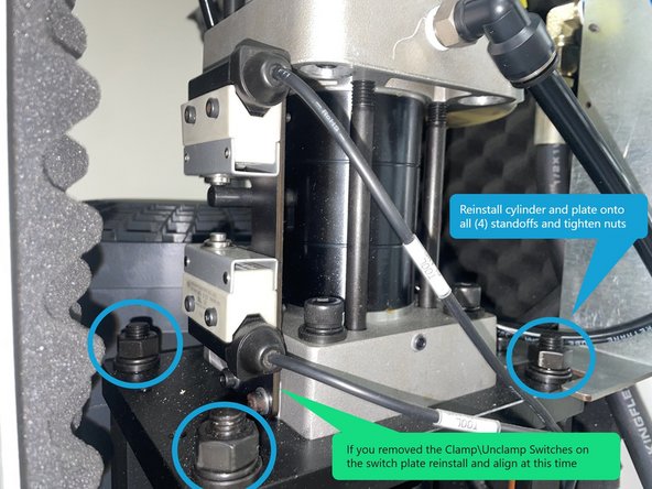
Reinstall the Clamp\Unclamp Cylinder with new Air Cylinder Kit onto the (4) large standoffs. Tighten the mounting nuts securely.
-
If you removed the Clamp\Unclamp Switches on the switch plate reinstall and adjust them at this time.
-
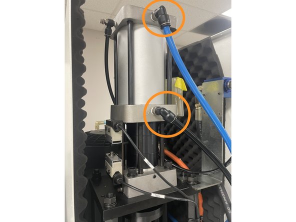
Reinstall the Blue and black Clamp\Unclamp air lines to the cylinder.
-
Reconnect the air to the machine at this time so the spindle bump out can be adjusted.
-
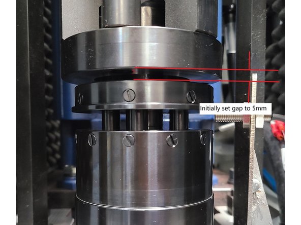
Adjust the Air Cylinder Kit so there's a 5mm gap between the cage assembly and the spindle.
-
Note: The 5mm gap is an initial adjustment, it may need to be adjusted further in the next step.
-
-
-
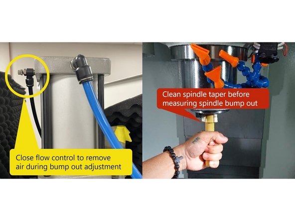
Prior to adjusting the spindle bump out, the through spindle air needs to be turned off so that the air pressure doesn't give a false reading during the bump out measurement. Locate the air Flo Control valve on the top of the Clamp/Unclamp cylinder and close it to remove the air pressure. See Photo 1
-
Clean the spindle taper to ensure it’s free of coolant and debris. Photo 1
-
There are (2) ways to measure the spindle bump out, one with a Bump Out Tool and one without. The next few steps show both ways to measure the bump out.
-
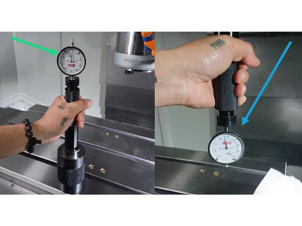
Measurement with Bump Out Tool: Clean a flat spot on the table and place the Bump Out Tool Calibration Gauge small opening down on the table. Verify that both the gauge and bump out tool tapers are clean. Insert the bump out tool into the gauge and zero the indicator. Record the small needle position on the indicator for reference.
-
Press and hold the spindle Unclamp button, then insert the bump out tool into the spindle. Measure bump out—it should read between 0.020" and 0.030". Verify the small needle position is in the same place as when the gauge was zeroed.
-
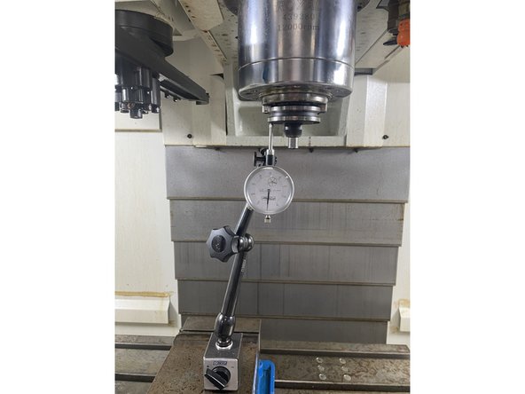
Measurement Without a Bump Out Tool: Put a 40 taper tool holder into the spindle. Then set up a dial plunger indicator on the tool holder and zero. To test the bump out, hold onto the tool holder and unclamp the tool and watch the indicator, it should move between 0.020" to 0.030".
-
If adjustment is needed, loosen the 4 clamp screws, and rotate the assembly up or down, to achieve the 0.020" to 0.030" bump out. Then apply 243 Loctite to the 4 M5X40 SHCS and tighten.
-
-
-
Once the bump out has been adjusted and the (4) M5X40 SHCS have been tightened, install (1) brass tipped set screw into the upper lock nut and tighten, then tighten the (2) brass tipped set screws in the lower lock nut.
-
For CTS machines: Reconnect the air and coolant fittings to the rotary joint.
-
For CTS Ready machines: Reinstall the air tube and support bracket carefully to avoid bending.
-
The air tube should be Stainless Steel not Aluminum
-
Replace any tie wraps cut during disassembly.
-
Confirm all hardware is securely fastened. Reinstall the front sheet metal cover. Clean the machine to complete the installation.
-