Introduction
This procedure details how to replace the computer module of a ProtoTRAK SMX CNC.
For a detailed drawing of the parts involved with the pendant assembly, please refer to the drawing that is attached at the end of this guide.
-
-
Turn off power to the machine and control.
-
-
-
Unplug all the connectors on the pendant arm side of the pendant.
-
Remove the pendant from the pendant arm by removing the four (4) 1/4 - 20 x 3/4" SCHS that secure it in place.
-
-
-
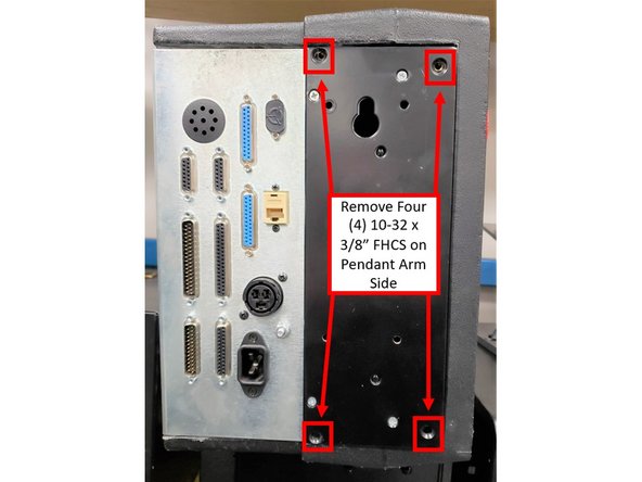
Place pendant assembly on a clean and secured table with the display pointing away from you.
-
Remove four (4) 10-32 x 3/8" FHCS from the pendant arm side of the SX Pendant that are securing the computer module to the LCD/enclosure.
-
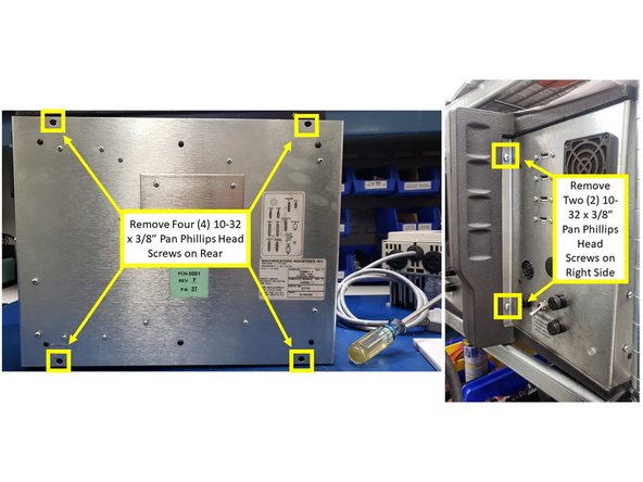
Remove four (4) 10-32 x 3/8" Pan Phillips Head Screws from the rear and two (2) from the right side of the SX Pendant that are securing the computer module to the LCD/enclosure.
-
-
-
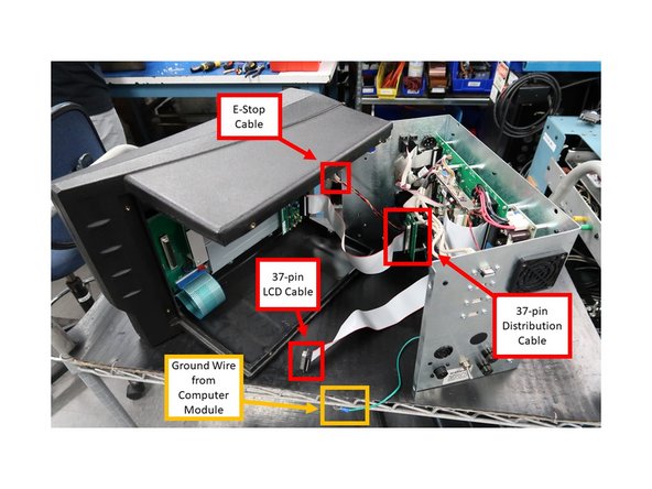
Pull the computer module a few inches and stop.
-
Pulling the computer module too far will damage the ribbon cables.
-
Reach from the top, and remove the 37-pin LCD cable, 37-pin distribution cable and the 9-pin E/Stop cables.
-
The above cables are to stay with the computer module.
-
Next, slide the module about 1/2 way out of the LCD/enclosure.
-
Remove the ground wire from the LCD/enclosure side.
-
Lastly, slide the unit completely out of the LCD/enclosure.
-
-
-
Replace computer module or LCD/enclosure.
-
Follow the instructions in reverse order when reinstalling the new computer module or LCD/enclosure.
-
Make sure that all connectors are properly seated before fastening the unit back in place.
-
-
-
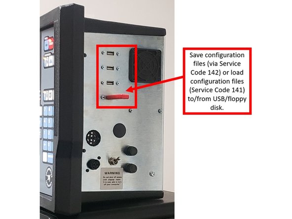
If applicable, you can save configuration files on a floppy disk or external drive via Service Code 142 prior to replacing the computer module, and/or load configuration files from a floppy disk/external drive via Service Code 141 on a new computer module after it had been replaced.
-
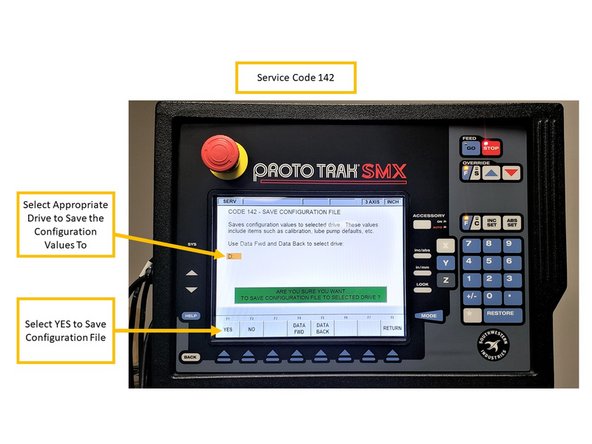
Service Code 142 allows you to save your configuration file to a floppy disk or external drive. The configuration file consists of items such as calibration and backlash constants. This code is used when a computer module or hard drive needs to be replaced. This stores the configuration file from the hard drive to the floppy disk.
-
Insert USB/floppy drive on the SX control. On the Service Code 142 screen, select the appropriate drive to save the configuration files to (D Drive will be available for most USBs), and choose YES.
-
It is a good idea to do this code after the machine is initially setup, so these values can be saved and used in the future.
-
If the computer or hard drive fails, then you will not have the ability to save the configuration file, and the machine will need to be re-setup when the computer or hard drive is replaced. If Service Codes 141 and 142 do not apply, please follow Step 8 of this guide.
-
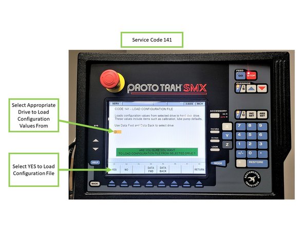
Service Code 141 allows you to load configuration files from the floppy disk or external drive to your hard drive. The configuration file consists of items such as calibration and backlash constants. This code is used when a computer module or hard drive has been replaced.
-
Insert USB/floppy drive on the SX control. On the Service Code 141 screen, select the appropriate drive to load the configuration files from (D Drive will be available for most USBs), and choose YES.
-
-
-
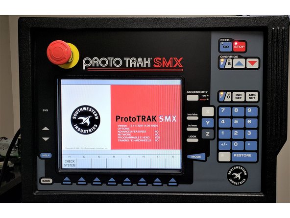
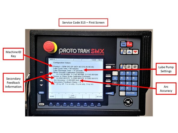
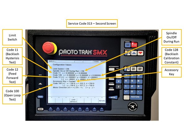
If running Service Codes 142 and/or 141 was successful on the new Computer Module, you can run Service Code 313 to display and confirm the current configuration files on your new computer module. Service Code 313 will feature two (2) screens:
-
Please note that the images provided on the left are used for reference information only; you would typically see values other than zero on both of the Service Code 313 screens.
-
The first screen of Service Code 313 displays the following information:
-
Machine ID Key, Lube Pump Settings (displays settings for Lube Cycle Time and Lube Discharge Time), Arc Accuracy (displays the measurement for Maximum Following Error on programs with sharp corners), and Secondary Feedback Information (Motor Encoder Calibration Constants, Secondary Feedback Calibration Constants, and enabling Secondary Feedback).
-
The second screen of Service Code 313 displays the following information:
-
Limit Switches (displays if limit switches are enabled for ram, saddle and table travel), if Spindle is enabled during Run Mode, Code 11 (measures how much motor motion is necessary to create table/saddle motion), Code 128 (displays backlash values for each axis), Code 12 (displays values and sets parameters for machine friction characteristics),
-
Accessory Key (displays the type of Auxiliary Function [Coolant, Air, Indexer] being used), and Code 100 (used to check the maximum feedrate of an axis and if the encoders are counting).
-
-
-
Per Step 6 above, If the computer or hard drive fails, then you will not have the ability to save the configuration file, and the machine will need to be re-setup when the computer or hard drive is replaced.
-
Machine must be calibrated using Service Code 123 and a calibration standard or other precision block.
-
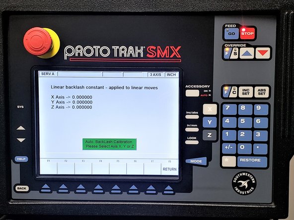
You must run Service Code 128 on your machine in order set up backlash values for each axis.
-
Please note that the recalibration process for the TRAK K3 SMX is going to be provided on an upcoming guide.
-