Introduction
This procedure details how to check connections and functionality of all axes as the first troubleshooting step for fixing Run Away Axis on a TRAK K3 with SX Control.
The TRAK K3 SMX uses 10+ cables to communicate between systems. It is often the case that what appears to be the failure of an electrical component is actually attributable to a poor connection. This poor connection tends to cause chronic or intermittent control problems, as well as motor and measurement problems.
For a detailed drawing of the parts involved with the Pendant Assembly and Cable Breakout Box, please refer to the drawings that are attached at the end of this guide.
-
-
Make sure the main power is turned off on the back of the electrical cabinet before plugging in the cables.
-
With the main power to the machine turned off, check all connectors that are bundled on the pendant (P/N: 24000-1) arm. Each cable mates to only one connector on the pendant display back panel. Please see first image on the left for a breakdown of the connectors on the pendant arm side.
-
Use the key that is located on the back of the pendant to match up the connectors with the correct ports.
-
-
-
The Cable Breakout Box (P/N: 24999) is located on the back side of the machine. On machines without the auxiliary function option, it consists of three (3) motor connections, three (3) limit switch connections, three (3) encoder connections and an E-stop connection. Please see first image on the left for a breakdown of the connectors.
-
Machines with an auxiliary function option have two (2) more outlets. A 110 V outlet for a coolant pump or air solenoid and an indexer outlet. See second image on the left for more information.
-
The coolant pump signal and indexer signal comes down from Umbilical #2.
-
-
-
There is a total of four (4) cables that need to be connected to the pendant for non-spindle control machines:
-
The following three (3) cables must connect from the Pendant to the Cable Breakout Box: Umbilical #1 (P/N: 22555-10) and #2 (P/N: 22555-10) cables, and AC to Computer (P/N: 20267) cable. Please see first image on the left for more information.
-
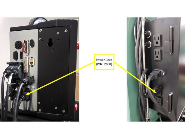
The Power Cord (P/N: 22608) must connect from the Pendant to the Electrical Box. Please see second image on the left for more information.
-
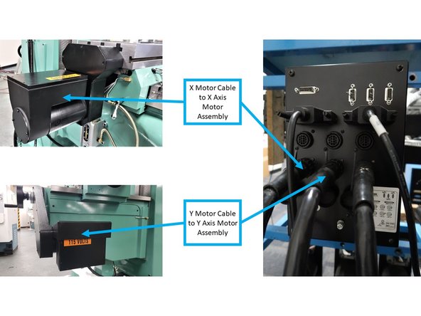
Connect the X and Y Motor Cables to the X and Y Motor Assemblies (P/N: 20296), as shown on the third image on the left.
-
-
-
The machine ID port (or called LPT) and parallel port (hardware key) will have a key plugged into it.
-
Make sure that the Machine ID Key (P/N: 22758-SKNEE2X) is plugged into the machine or it will not run. Spindle control machines use a different Machine ID Key than non-spindle control machines.
-
Make sure that there is a Hardware (Option) Key (P/N: 22648) plugged into the parallel port of the pendant. This key activates any converters or options ordered. The key must be programmed according to the type of machine it is on, and the options ordered.
-
-
-
Turn off and unplug the system from the wall.
-
Do not plug and unplug connectors with the system power on. This may cause damage to the connector board, and harm to the technician.
-
Visually inspect the connections for excessive debris, moisture, or obvious damage.
-
Carefully clean any chips away from the connectors.
-
One-by-one, take out each connector and then plug them back in. Do the same at the computer/display.
-
Make sure to tighten up the screws on each of the connectors.
-
Whenever you replace a cable or reroute a cable, it is very important to keep the power cables and logic cables separated from each other. Mixing of the power and logic cables may cause noise from the power cables to interrupt the signals in the logic cables. This can lead to intermittent axis faults or repeatability problems.
-