Introduction
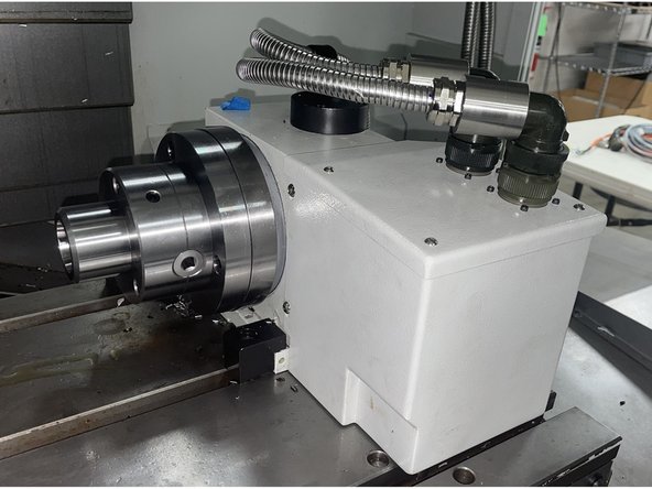
With this procedure the user will be able to adjust the backlash on the VMC2 4th Axis.


Parts
No parts specified.
-
-
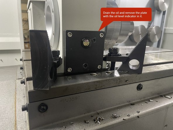
To adjust the backlash on the VMC2 4th Axis you need to drain the oil and remove the black plate with the oil level indicator in it.
-
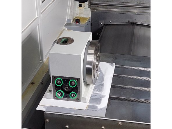
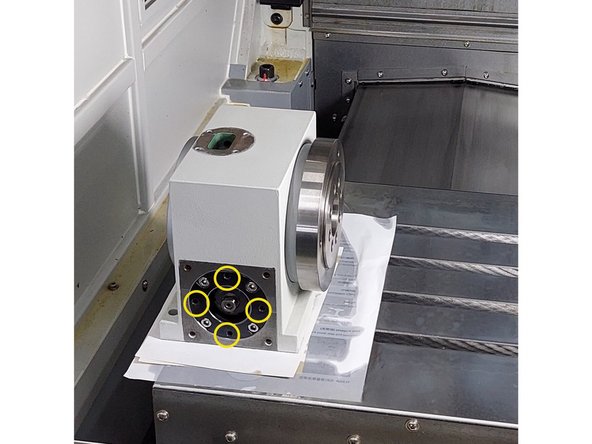
Beneath the plate with the oil level indicator on it there are 8 screws, 4 socket head cap screws and 4 set screws.
-
The 4 socket head cap screws (circled in Green) are for the forward movement or decreasing of the backlash.
-
The 4 set screws (circled in Yellow) are for the reverse movement or increasing of the backlash.
-
-
-
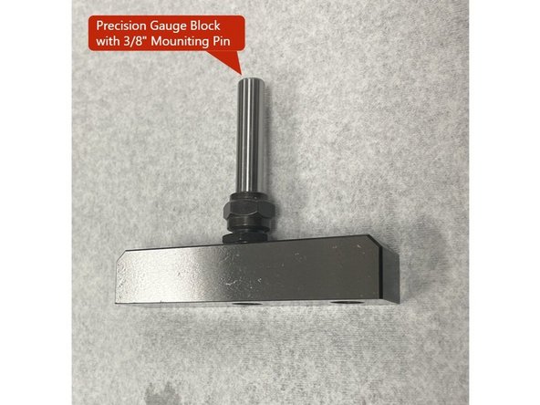
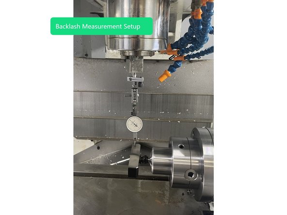
In order to measure the backlash of the VMC2 4th Axis you need to install a precision T-Block with a 3/8 diameter pin for holding it in the collet of the 4th Axis, and install a 0.0001" dial indicator to the spindle. See Photo
-
To measure the backlash of the 4th Axis move the Y axis and level the precision gauge block by measuring both ends and getting them as close to zero as possible.
-
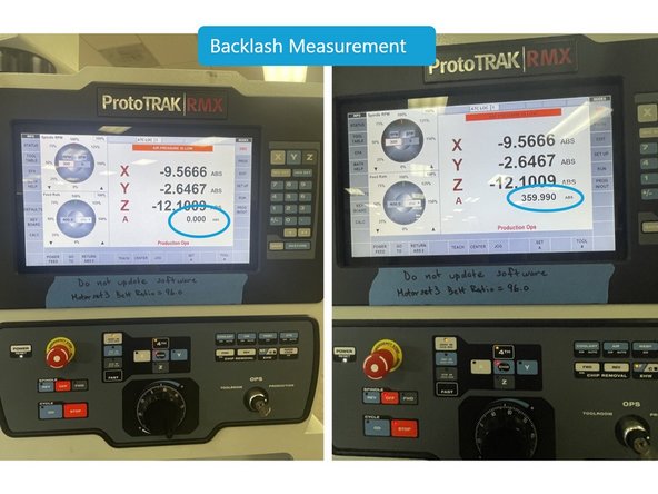
Next set the indicator on one end of the gauge block. Then set the EHW to the A Axis and set it to the 0.0001" setting. Now move the A Axis with the EHW until the indicator stops reading (about 0.001"), you may need to move both directions to find the point where the indicator stops reading.
-
Once the indicator stops reading zero the A Axis and continue moving in that direction until the indicator starts to read again. This difference is your backlash. This should be within 0.01 and 0.006 degrees. If you are outside of this the backlash needs to be adjusted.
-
In order to decrease the backlash you need to loosen the set screws about a 1/4 turn and tighten the the socket head cap screws about a 1/4 turn. Start tightening the 4 SHCS slowly and in a crossing pattern. You may need to tighten the SHCS and loosen the set screws a few times to get to the correct backlash.
-
To increase the backlash to the reverse as the above step.
-
-
-
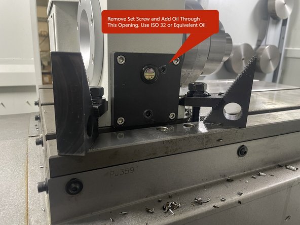
Once the backlash has been set, reinstall the black plate with the oil level indicator in it.
-
Then remove the upper set screw and add ISO 32 oil into the 4th Axis until it is between the high and low marks on the oil level indicator. Put teflon tape on the set screw and reinstall.
-
Once the oil level is filled, remove the Dial Indicator from the spindle and the 5C Collet from the 4th Axis the adjustment is complete.
-

Team
