-
-
This adjustment is performed when the ATC arm drifts or does not stop consistently at the beginning or end of its rotation.
-
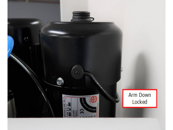
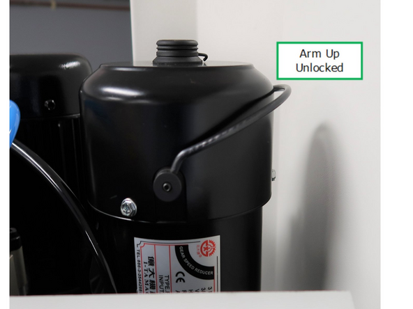
Before adjusting the signal wheels, verify that the ATC motor brake is fully engaged and operating correctly.
-
-
-
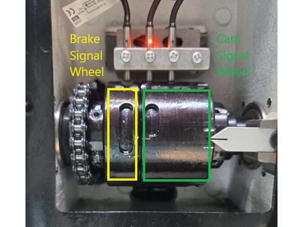
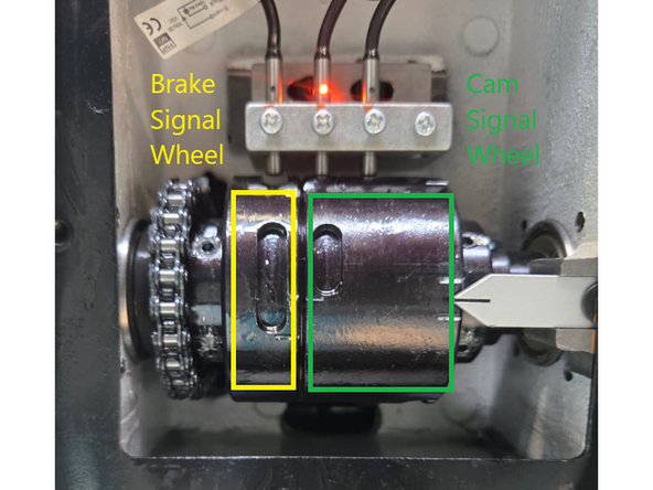
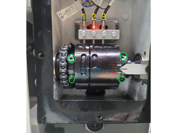
The ATC arm uses two signal wheels to control position sensing during the tool change:
-
Left Wheel = Brake Signal Wheel
-
Right Wheel = Cam Signal Wheel
-
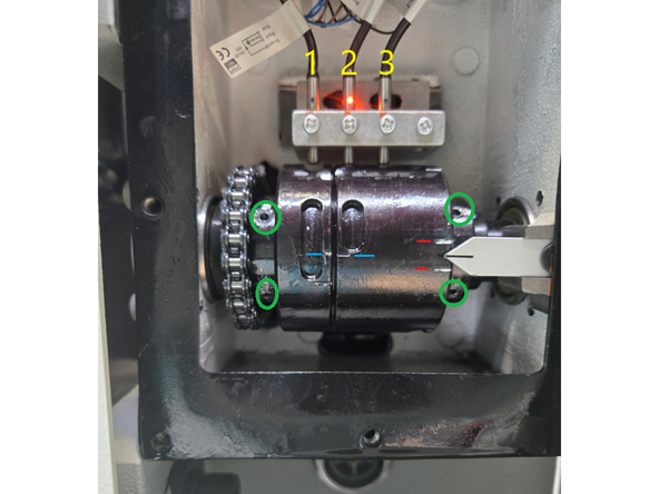
Each wheel rotates past a fixed sensor block containing three sensors. These sensors detect the arm’s position and trigger the next motion in the ATC sequence.
-
-
-
The Brake Signal Wheel should always be adjusted first. The wheels are secured to the arm shaft by green-circled set screws, loosening the screws allows each wheel to rotate independently of the shaft for fine timing adjustments.
-
Left screws adjust the Brake Signal Wheel, Right screws adjust the Cam Signal Wheel
-
Loosen the left-side set screws on the Brake Signal Wheel.
-
Adjust the timing by moving the wheel slightly UP or DOWN:
-
Brake engages too early? Move the brake wheel UP.
-
Brake engages too late? Move the brake wheel DOWN.
-
Use the two timing reference marks on the wheels as the default starting point — these are small gray dash indents on the wheel edges, shown in blue in the picture for clarity.
-
Tighten the set screws and verify the brake engages and holds correctly at both the start and end of the ATC arm motion.
-
-
-
This adjustment should only be performed if correcting the Brake Signal Wheel timing did not resolve the issue.
-
Confirm the ATC arm is already in the Home Position — centered between the spindle and the tool pot. This is the default stopping point after a completed tool change.
-
Loosen the right-side set screws on the Cam Signal Wheel.
-
Rotate the Cam Signal Wheel until only the center sensor (2) is lit. This typically places the wheel’s arrow between the two small red reference marks.
-
Tighten the set screws and verify that the middle sensor switches cleanly on and off as the arm enters and exits the Home Position.
-

Team
