Introduction
This document is to specify the removal and installation procedure for 30120 Lathe Spindle Bearings. See Step 20 for the Bearing Preload Adjustment Procedure.
All bearing and spindle work must be done in a clean environment.
Tools
- WD40 Spray Can
- Freezer
- 5 gallon bucket
- Electric Oven
- Dead Centers × 2
- Depth Micrometer
- Mobilith SHC 100 Lithium Complex grease or similiar
- 30-250 in/lb torque wrench with 1/2' or 13mm socket
- 0-150 ft/lb torque wrench
- 200-600 ft/lb torque wreench with special hook spanner wrench
- 0-75 in/lb torque wrench
- 0.0001 dial indicator with mag base × 3
- SWI 31090 - 30120 Spindle Replacement Tooling Kit
- Brass punch
- Hammer
- Set of Metric Allen Wrenches
- 10mm combination wrench
- Set Metric hex drivers
- 3/8 drive ratchet
- 32009 Tailstock torque drive
Parts
-
-
All bearing and spindle work must be done in a clean environment.
-
If only performing bearing preload adjustment, see instructions starting at Step 20 under Bearing Preload Adjustment.
-
Before starting this procedure:
-
Place the outer races of the front and rear tapered roller bearings in a plastic bag and coat with a light coat of WD40 and put in a freezer overnight.
-
Drain oil from headstock
-
Remove any tooling or tool holders from the carriage.
-
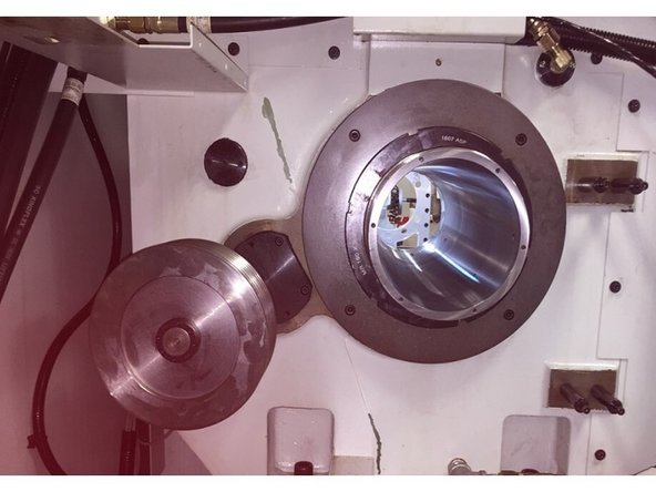
Remove the chuck guard, ring and chuck guard collar pieces from the front of the spindle as shown.
-
-
-
Remove the sheet metal surrounding the rear chuck as shown.
-
-
-
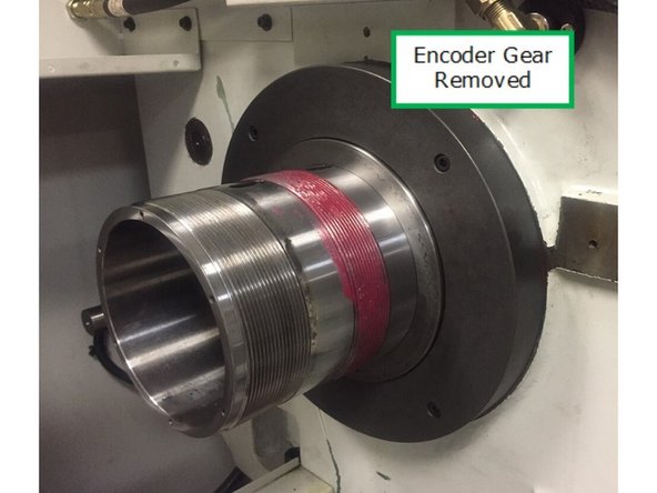
Remove the spindle encoder assembly with belt and set aside.
-
Second photo after removal.
-
-
-
Using 2 M10 eye bolts, a strap or chain, and a crane remove the head stock cover.
-
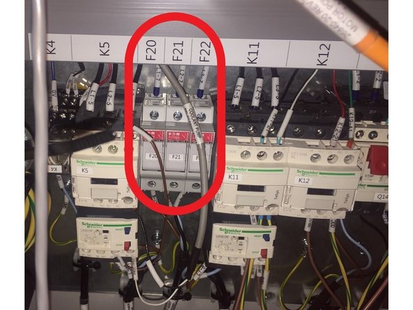
Turn power off and pull fuses 20, 21, and 22 to disable the headstock oil pump.
-
Disabling the headstock oil pump so you can move the X and Z axis without pumping oil all over the place.
-
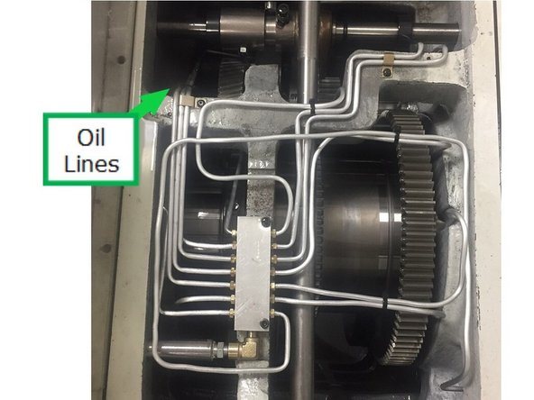
Remove oil lines from manifold inside headstock. The lines will need to be removed individually. Keep track of how the lines are routed to put them back correctly upon reassembly.
-
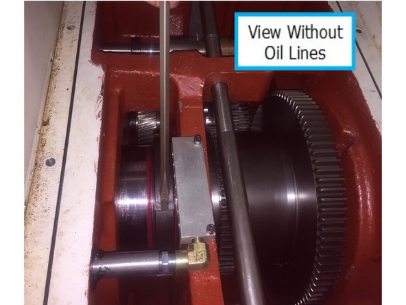
After oil lines are removed.
-
-
-
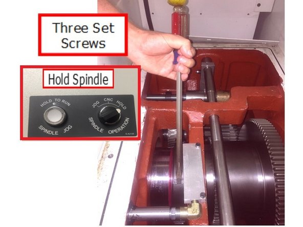
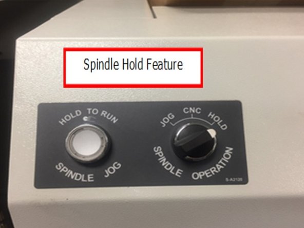
Use spindle hold feature (Inset photo)on the lathe to prevent the spindle from turning when loosening the lock nuts.
-
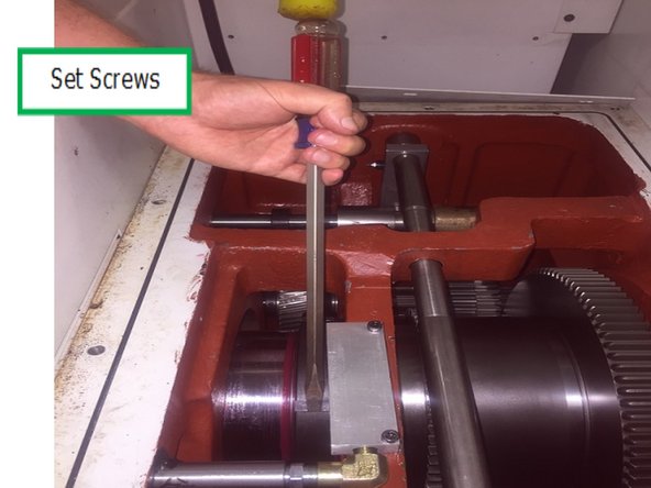
Loosen the 3 set screws (not shown) on the high/low gear lock nut and loosen the lock nut using a brass punch or screw driver and hammer. Remove the lock nut from the threads.
-
Loosen the set screws on the spindle bearing lock nut.
-
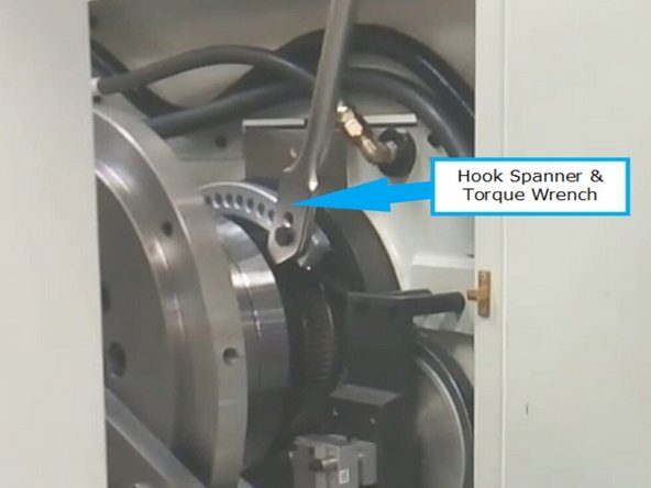
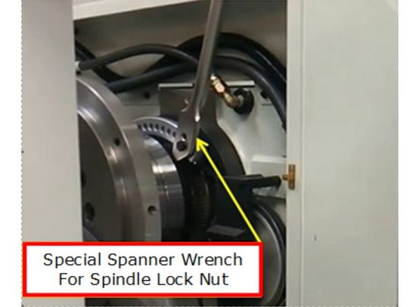
Using the special hook spanner and torque wrench loosen the lock nut and remove.
-
-
-
Remove the 6 socket head cap screws that attach the front spindle cover.
-
Install spindle puller assembly to the X axis carriage. Set spindle puller assembly on carriage, and firmly tighten the (6X) 3/8-16 SHCS to clamp assembly to carriage.
-
Move Z axis towards spindle and align the X and Z axis to the spindle. Make sure the indexing boss on spindle face is pointing up. Secure to spindle with (9X) M20x50 SHCS and M20 washer.
-
Set the X and Z axis to zero once the spindle alignment tool is secured to the spindle.
-
-
-
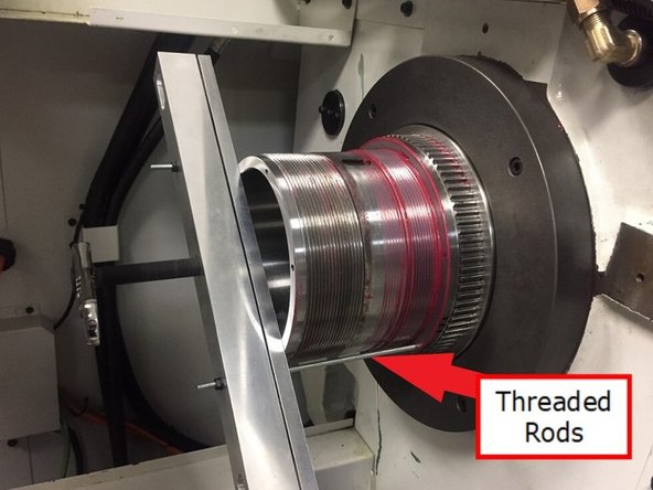
Install 31093-2 gear puller crossbar to back of spindle with (2X) M5x18 SHCS. Attach 31093-5 gear puller pullbar and thread in the (2X) M5 threaded rods, using hex nuts to thread them into the encoder pulley.
-
On early machines the encoder pulley will not be drilled to accept the encoder gear puller.
-
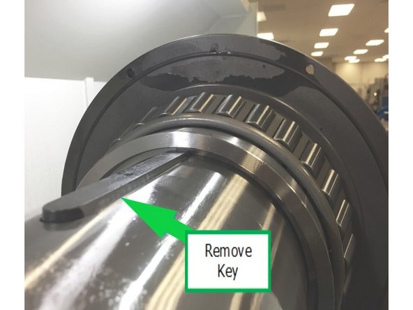
Thread in 32005 forcing screw to remove the encoder pulley. Once the pulley is removed, remove the exposed key from the spindle. Remove encoder pulley assistive tooling and set aside. It will be used again later.
-
Note the orientation of the encoder gear and oil slinger / labyrinth seal when removing.
-
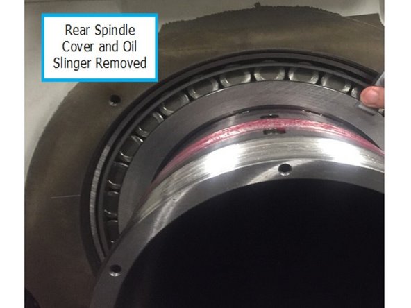
Remove the rear spindle cover and oil slinger.
-
-
-
The next few steps of the procedure are best done with 2 people so one could be moving the Z axis with the handwheel and the other can be guiding the gears, spacers etc. and directing the person moving the Z-axis to avoid damaging the gears, spacers etc. in the headstock.
-
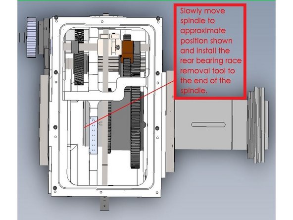
Using the Z axis handwheel in DRO slowly start to move the spindle out of the head stock to remove the rear bearing from the spindle. Once the spindle has moved back far enough that the rear bearing is free, remove the rear bearing, high/ low gear lock nut and spacer.
-
Now move spindle back far enough that 31097 push plate can be installed onto the end of the spindle with (6X) M5x30 SHCS and washer. Once installed, move spindle back towards the rear bearing race and slowly push the race out of the casting.
-
-
-
Once the race is out of the casting, remove 31097 push plate. High gear can now be removed. Slowly push high gear through the casting and to the end of the spindle. Take caution when removing high gear from the end of the spindle - high gear weighs about 30lbs.
-
-
-
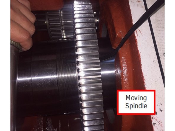
Now slowly start to move the spindle out of the casting until low gear is free of the main drive key for high and low gears.
-
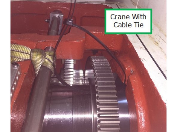
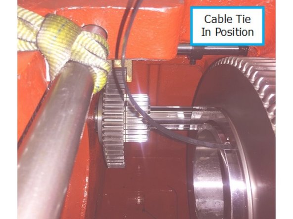
Install the 48” heavy duty cable tie through low gear at the keyway in the gear and connect the ends of the cable tie to create loop so this can be used as a handle to help remove low gear from the spindle and out of the headstock.
-
Take caution when removing low gear, low gear weighs approximately 50lbs. A crane could be used to hook through the cable tie to aid in the removal and installation of low gear.
-
Cable tie is installed on low gear.
-
Once the cable tie is installed on low gear, slowly move the spindle out of the head stock while holding onto the cable tie until you can gently remove low gear from the spindle. Once low gear is removed from the spindle and is out of the head stock, fully remove the spindle from the head stock completely.
-
-
-
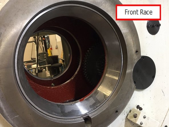
Once the spindle is removed from the casting, remove the front bearing race from headstock casting using a brass bar and hammer
-
Remove the key for high and low gear from the spindle using jackscrew pre-installed on key. Remove the spacer between low gear and the front bearing.
-
-
-
Place protective barrier (like a piece of plywood or like) on top of bed ways to protect machine.
-
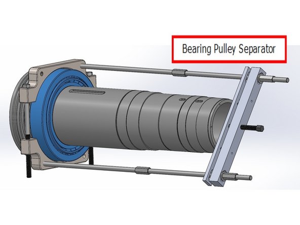
Loosely thread (2X) 5/8-11 x12 HHCS to attach 31093-1 bearing pulley separator halves. This can now be slid onto spindle and laid over front bearing. Thread in HHCS but allow bearing puller to rotate on bearing. Install the 31093-2 crossbar and 31093-5 pullbar as used before on encoder pulley removal.
-
Caution should be used when catching bearing – it is heavy and can easily damage hands or the machine ways.
-
Install the 5/8-18 threaded rods as shown, using the coupling nuts to reach full length. Tighten the HHCS and install rear coupling nuts with washers. Apply small amount of oil to spindle to allow bearing inner race to slide over spindle.
-
Begin by slowly tightening the forcing screw and removing the bearing. Forcing screw can be loosened and rear coupling nuts can be repositioned, if necessary. Once fully released, disassemble bearing puller tooling and slide off bearing.
-
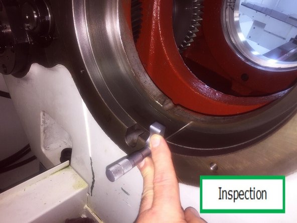
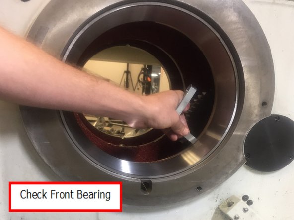
Inspect the headstock bearing race bores for nicks, burrs or other forms of damage. Using a depth micrometer, check the bore depths in 4 places at 90° intervals and note any differences over .005”. Do this for both front and rear bearing race bores.
-
-
-
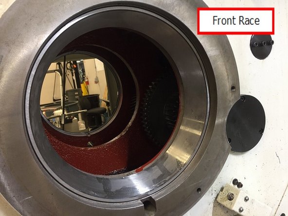
Verify the front bearing race bore is clean and free of debris, lightly stone any nicks or high spots.
-
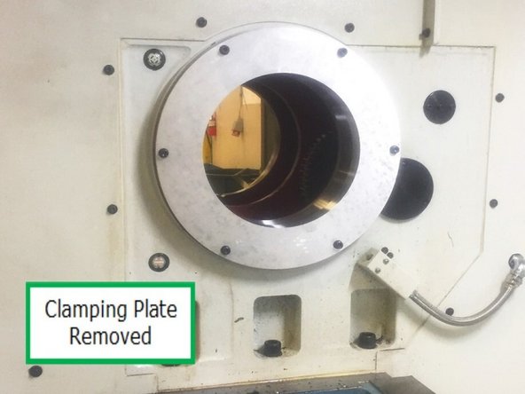
Remove front bearing race from freezer and install in the casting. Use 31099 clamping plate and (6x) M8x30 SHCS and washer to seat race and hold in place for at least 10 minutes while the race comes back up to room temp.
-
Remove clamping plate.
-
Note: Do not install rear bearing race at this time.
-
-
-
Do not heat the bearings above 180° F (82° C). AFTER the bearings are heated, apply a generous coat of DTE 24 oil to the bearing and inner race before installing onto the spindle.
-
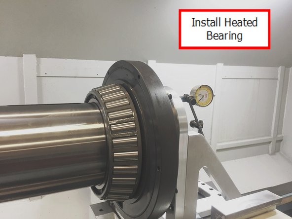
Place the front inner bearing in an oven and warm up to 150° F (66° C) over a period of about a half an hour.
-
Install Front Inner bearing on spindle and slide back until it is firmly up against the shoulder of the spindle.
-
Allow bearing to cool to ambient temperature (about 30 mins) and coat with oil again.
-
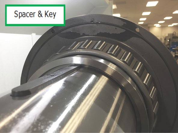
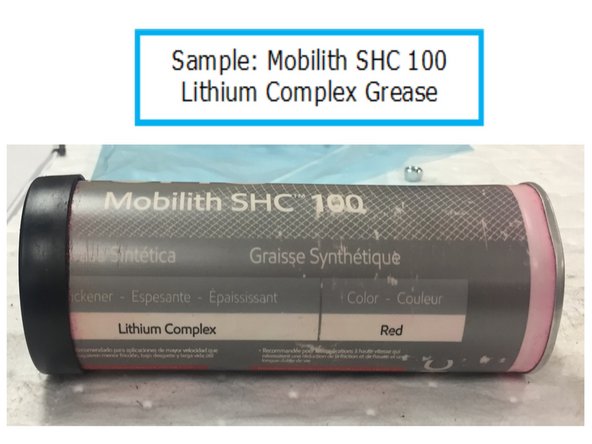
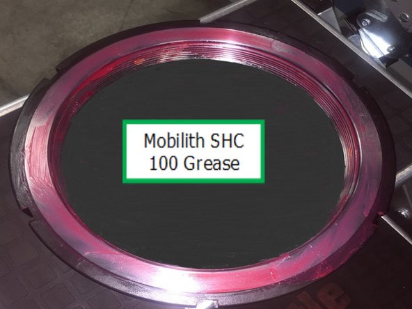
Install spacer and key onto spindle and coat the front spindle cover o-ring with Mobilith SHC 100 Lithium Complex Grease or Similar.
-
Mobilith SHC 100 Lithium Complex Grease sample.
-
-
-
Remove the front bearing race retaining tool. Using a depth micrometer measure that the race is properly seated. Check in 4 places around the perimeter of the race at about 90o, the readings should not be different by more than .005”.
-
Also, using a .005 feeler gauge, verify that the outer race is flush with the shoulder of the bearing race bore. Measure around the perimeter fully.
-
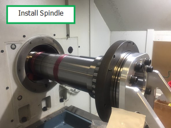
Using the handwheel in DRO slowly move the spindle into the casting until low gear can be installed onto the spindle. Once low gear is on the spindle continue moving the spindle until it gets near the drive key in the spindle, remove the cable tie from low gear and slide low gear over the key.
-
Continue moving the spindle into the casting guiding low gear until you reach the zero you set when you installed the spindle puller assembly.
-
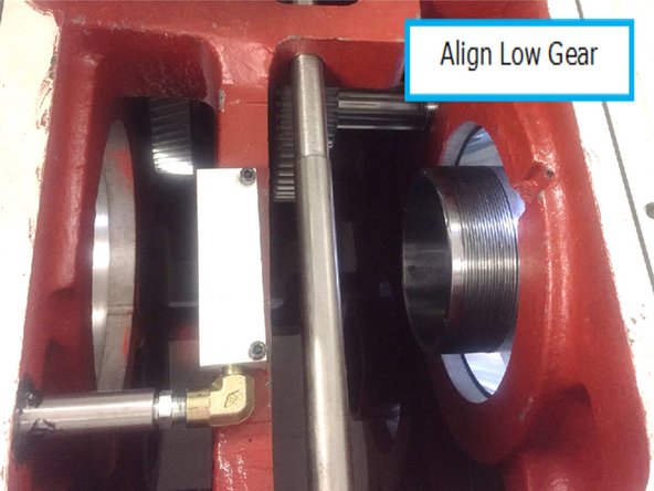
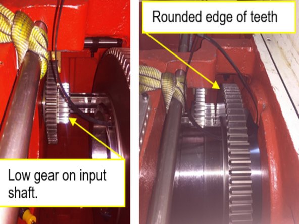
Note: Be sure to properly orient low gear so that the rounded ends of the teeth are facing low gear on the input shaft.
-
-
-
Note: Be sure to properly orient low gear so that the rounded ends of the teeth are facing low gear on the input shaft
-
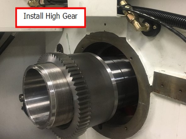
Install high gear onto the spindle and slide through the casting and align high gear with the drive key and seat against low gear. Once high gear is in place install the spacer.
-
Next apply Mobilith SHC 100 or Similar grease to the spindle threads, lock nut threads, and ground face of the lock nut.
-
-
-
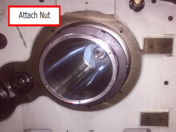
Thread nut onto spindle and tighten with brass punch or screwdriver and plastic tipped hammer
-
Note: You may not be able to tighten the set screws at this time because the spindle can’t be rotated due to it being mounted in the spindle removal tool.
-
-
-
Verify the rear bearing race bore is clean and free of debris, lightly stone any nicks or high spots
-
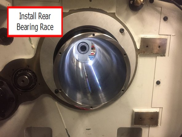
Remove rear spindle bearing race from freezer and install into casting and hold in place using 31098 clamping plate and (4X) M8x30 SHCS and washer. Leave clamping plate for at least 10 minutes for bearing race to come up to room temp, then remove.
-
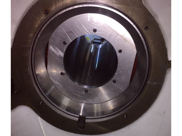
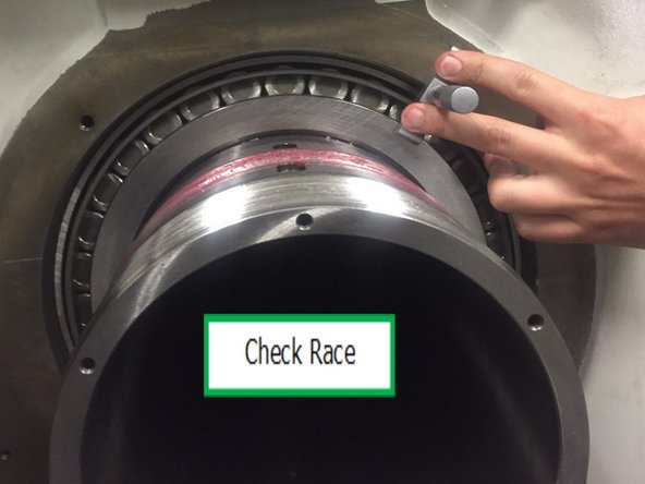
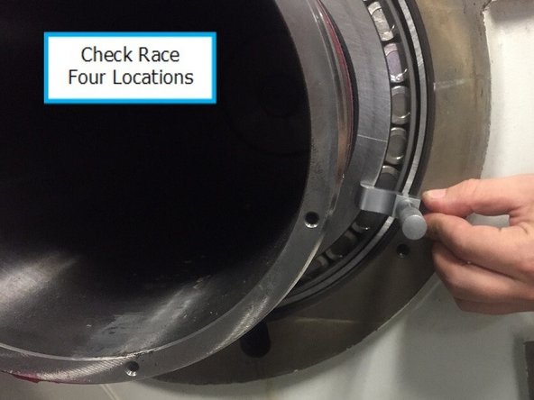
Measurement of the bearing race should be done prior to installing the tapered roller bearing not after as the pictures show.
-
Using a depth micrometer measure that the race is properly seated.
-
Check in 4 places around the perimeter of the race at about 90°, the readings should not be different by more than .005”.
-
-
-
Place the rear inner bearing in an oven and warm up to 150° F (66° C) over a period of about a half an hour.
-
Caution! Do not heat the bearings above 180° F (82° C). AFTER the bearings are heated, apply a generous coat of DTE 24 oil to the bearings before the bearings are installed onto the spindle.
-
Install rear inner bearing on spindle and slide until it is firmly up against the inner race of the bearing.
-
Allow bearing to cool to ambient temperature (about 30 mins) and coat with oil again.
-
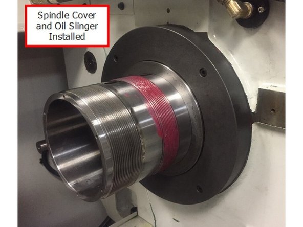
Reinstall the rear spindle cover and oil slinger. Install encoder gear key and encoder gear.
-
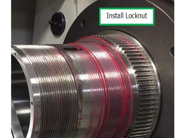
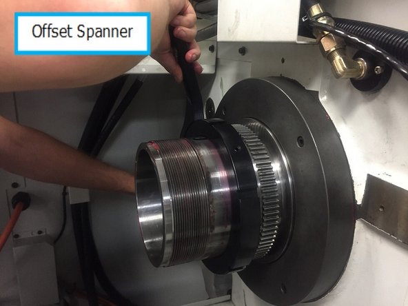
Grease the spindle threads, lock nut threads and locknut face and install the locknut onto the spindle and tighten until snug against the encoder gear.
-
31089-5 Offset spanner may help with threading the locknut over the grease.
-
-
-
Remove the (9X) M20 SHCS and washer that attach the spindle puller assembly to the spindle and move the Z axis back away from the spindle. Remove the spindle puller assembly from the X axis carriage. Reinstall 6 socket head cap screws in front spindle cover and tighten.
-
Tighten the 3 M10 set screws on the high/low gear locknut. Reinstall oil lines to manifold. Refill Headstock to low fill line in sight glass with ISO 32 oil. Reconnect fuses 20, 21, and 22 to headstock oil pump. Press the power reset button to enable servos and turn on the headstock lube pump. Verify that oil is flowing to the spindle bearings.
-
Bearing Preload Adjustment:
-
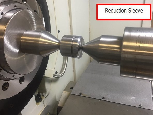
Install a reduction sleeve and dead center into the spindle, and a dead center in the tailstock. Use the carriage to move the tail stock so that the dead center points are about 6.0” apart. Loosely install the 31089 bearing assembly tool between the dead center points and lightly tighten the tail stock quill to hold the tools in place.
-
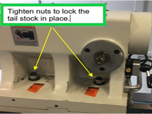
Lock the tailstock firmly in place. It’s very important the tail stock doesn’t move during the pre-load adjustment. If it does move, the pre-load adjustment will not be accurate.
-
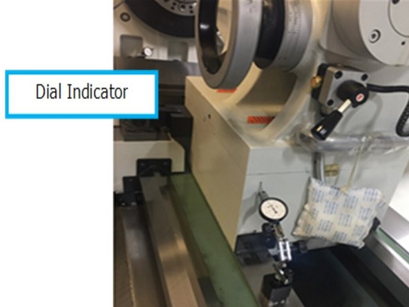
Set up a dial indicator to measure the base of the tail stock and set zero.
-
-
-
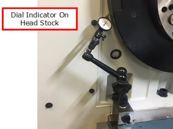
Set up a .0001” dial indicator on the front of the head stock casting. We want to see if the head stock casting flexes during the preloading process and we want to verify that when we release the tail stock that the casting flex, if any, returns to zero.
-
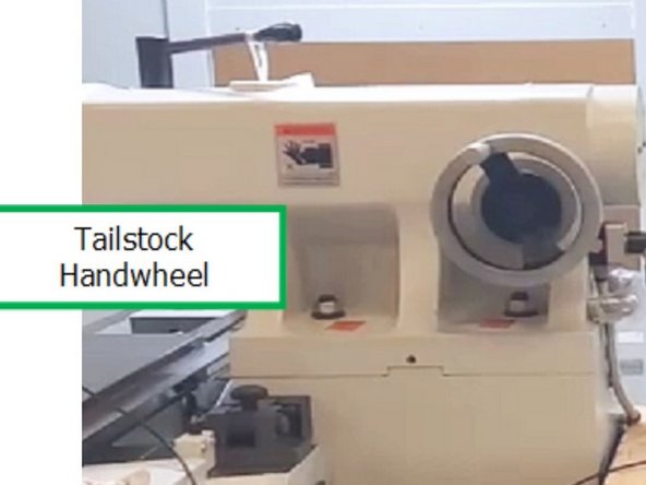
Remove the handwheel from the tailstock.
-
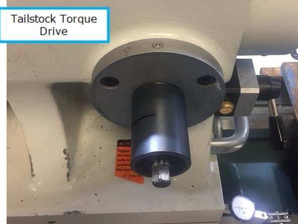
Install 32009 tailstock torque drive tool as shown in photo.
-
-
-
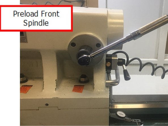
Set the 30 – 250 inch pound torque wrench to 55 inch pounds. Attach the torque wrench to the tailstock torque drive tool with a 13mm socket and torque the tail stock quill to 55 in-lbs. Rotate the spindle about 10 rotations in the forward and reverse directions. The 31088 torque bar was designed to assist with this.
-
It can be installed on the rear of spindle with (2X) M5x18 SHCS. It can accept any 3/8” square drive tool such as a ratchet. Continue increasing by 20 in-lbs increments and rotate the spindle in both the forward and reverse directions 10 times until you reach 1200 lbs of force, at this point lock the quill on the tail stock in place.
-
Important: Make sure to rotate the spindle about 10 revolutions in both the forward and reverse directions at each 20 in-lb increase. When you reach 235 in-lbs check the dial indicator on the tail stock to verify the tail stock hasn’t moved, if it hasn’t the front spindle bearing is now properly seated and preloaded.
-
-
-
Using the special spanner wrench and the spindle hold feature to prevent the spindle from rotating, torque the spindle lock nut to 200 ft-lbs to seat the bearings, then rotate the spindle forward and backwards about 10 times each direction. 31088 torque bar can be used here as well.
-
Then torque the lock nut to 225 ft-lbs, rotate the spindle about 10 times in each direction again. Continue increasing the torque on the lock nut by 25 ft-lb increments until you reach 400 ft-lbs rotating the spindle forward and backwards at least 10 revolutions with each increase.
-
-
-
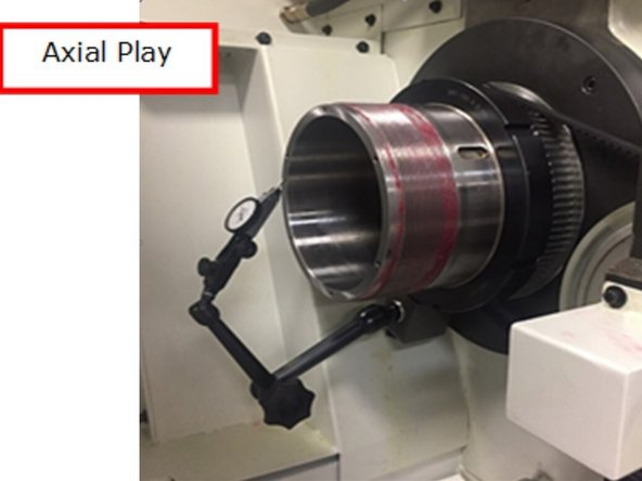
Set up a .0001” dial indicator on the back of the spindle shaft to check if there is any axial play in the spindle as the front bearing preload applied by the tailstock quill is released. While holding the spindle from rotating, unlock the tailstock quill and slowly pull it back.
-
Check the indicator to see if it had moved. Also check the indicator set up on the front of the headstock and verify that if there was any deflection of the headstock(Phil as?) it returns back to zero. Lastly apply force to the rear of the spindle by pushing on the spindle and check to see if the spindle moves forward by checking the indicator.
-
Note: If the indicator did move, it means that the spindle still has axial play, indicating that there is a problem with this installation. This requires that the spindle bearing lock nut be loosened and steps 18 - 23 must be repeated. If there is still axial play after the second time, contact engineering for advice.
-
-
-
If there is no axial play, check the rolling torque with spindle in neutral. 31088 torque bar is used for this, and can be mounted to front or rear of spindle, and torque meter can be inserted. The rolling torque should be in the 45 to 55 in-lbs range.
-
If the rolling torque is in the correct range progressively snug and tighten all of the set screws in the outer spindle lock ring. Tighten set screws to 20 ft-lbs. Check the rolling torque again it should still be within 45 – 55 in-lbs.
-
Important! In properly installed bearings, the difference between breakaway torque and rolling torque should be relatively small (around 2-4 in lbs. 3-5 kg cm) however on this machine since the chuck is so much larger and heavier the breakaway should be between 65 and 75 in-lbs.
-
Important! If the breakaway torque is much greater than the rolling torque, over 75 in lbs. (34-40 kg cm), it indicates that the bearings are not seated correctly and need to be reinstalled, paying particular attention to proper seating of bearing outer races.
-
-
-
Reinstall spindle encoder, belt and adjust belt tension.
-
Check oil level and top off if needed. Reinstall headstock cover.
-
Reinstall the chuck guard, ring and chuck guard collar pieces to the front of the spindle.
-
Reinstall the sheet metal surrounding the rear chuck and silicone the seams to prevent any coolant that gets into this area from leaking.
-
Important Note: Spindle bearings must be run-in properly before the lathe can be used in production; please see ES 427 for the 30120 Spindle Running-in procedure. This procedure applies to a new bearing installation only. Preloading of previously installed and run-in spindle bearings may result in a lower rolling torque measurement.
-


