-
-
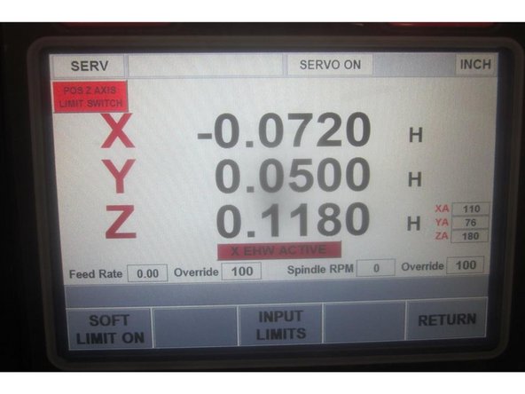
Power up the machine and home it. Raise the Z axis in service code 505 until the limit switch lights and note the index angle. If the brake has completely failed, the bridge will drop when the E-stop button is pressed.
-
If the brake has failed, raise the bridge in service code 505 and support the bridge with lumber or other suitable material. Set up so you have access to the motor, brake and cast housing.
-
Use service code 505 to jog the Z axis. Once the bridge is resting on lumber note the index angle.
-
Leave the power on and the servos activated.'''
-
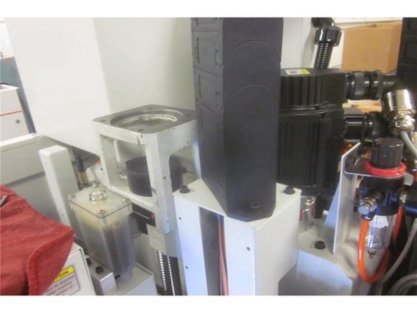
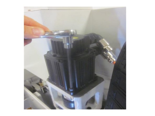
Loosen the two (2) lower screws on the motor coupler. Remove the four (4) screws that attach the motor to the brake housing.
-
-
-
If you need to only replace the Z motor follow this step. Otherwise go to step 3. Lift off the motor. Shut down the power at the main disconnect switch.
-
Carefully unscrew the (2) two power cables and remove the motor. Loosen the upper coupler screws and swap out the coupler to the new motor.
-
Position the coupler leaving 1/8 to 3/16 inch of the motor shaft showing between the coupler and the motor and a .100" gap between the coupler halves and plastic spider. Re-connect the cables and install the motor. Secure all fasteners. Power up the machine. Activate the servos.
-
Go to and follow steps 6 through 8 to finish this guide.
-
-
-
Note: The bridge must be supported by lumber or other suitable material before proceeding.
-
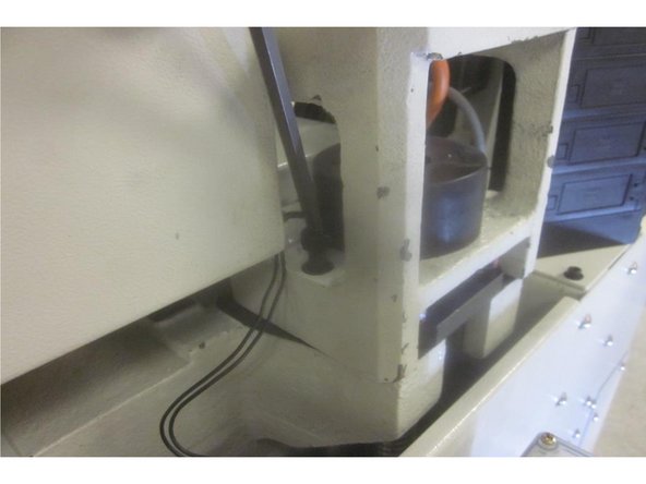
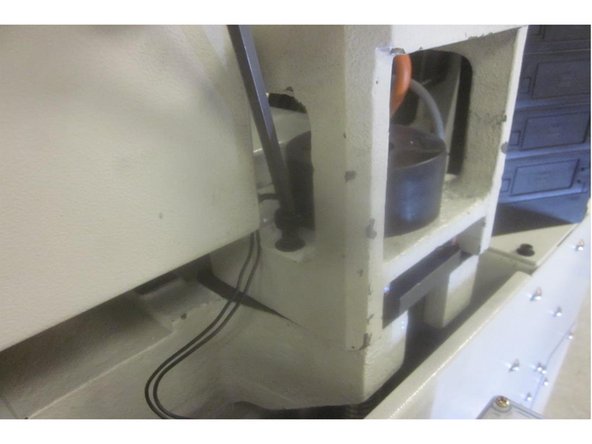
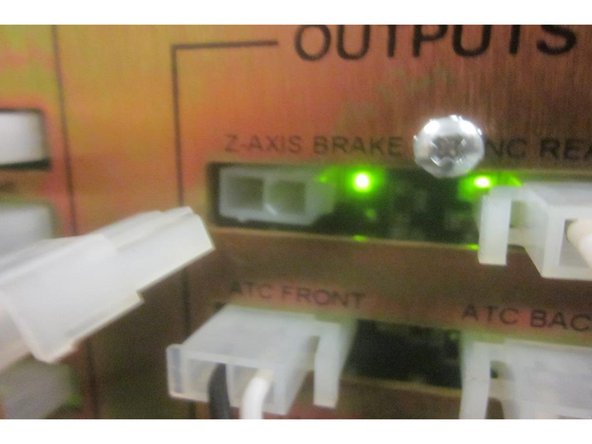
Disconnect the brake wire from under the servo box. When you do, power will be cut and the brake will engage. Note: A failed brake will slip.
-
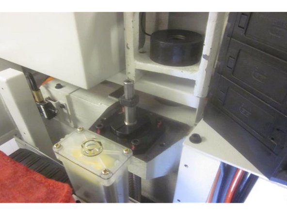
Lift the motor / coupler assembly off the housing and set aside.
-
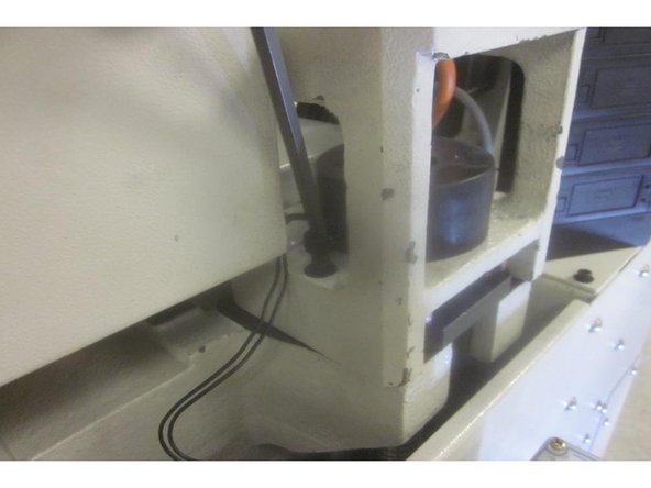
Remove the three (3) screws attaching the cast brake housing to the column.
-
Remove the brake housing assembly and place on a work table.
-
-
-
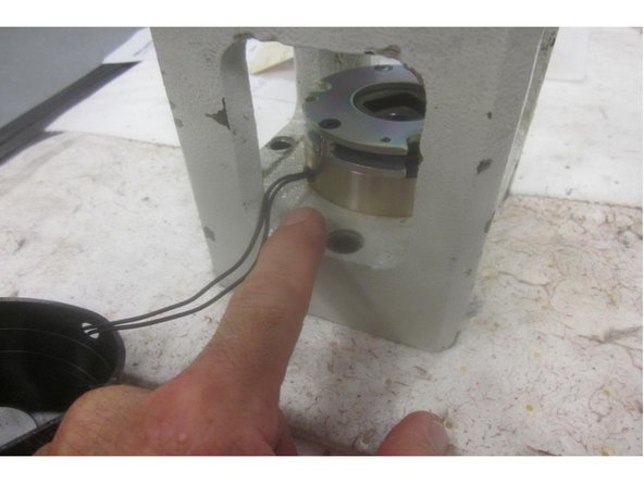
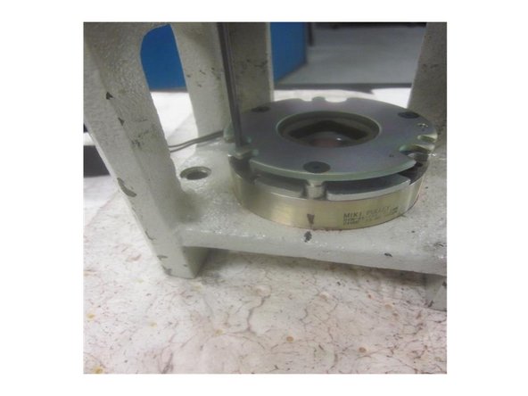
Remove the rubber brake cover taking care of the brake wire. Orientate the brake wire location on the housing. Remove the three (3) small screws attaching the brake to the housing. Lift off the brake and clean the machined surface.
-
Lightly lubricate all fasteners and install the new brake onto the housing. Make sure the wire is in the correct location. Install and tighten the screws securely.
-
Install the brake housing on the machine. The friction disc may not line up on the new brake. If this happens plug in the brake wire. Power to the brake will allow it to float and enable correct alignment. Install the 3 screws while centering up the housing .
-
-
-
Test fit the motor alignment on the brake housing. It should slide on easy and rest flush on the housing. If the alignment is good install the brake housing.
-
If the alignment is off, loosen the housing mounting screws ( with power "on" to the brake allowing it to float) and align the whole assembly. Tighten the housing screws securely. Install the rubber brake cover and re-connect the wire.
-
Check the motor alignment again and repeat this step if necessary. Once aligned, install the motor attaching screws and tighten to 18 ft. lbs. Tie off the brake wire with a zip tie. Tighten the lower coupler screws.
-
-
-
When all parts are back together, go to service code 203 and home the machine. Go to service code 505. Raise the Z axis until the limit switch lights. Write down the index angle number.
-
If the number is in spec (180 + or-45 135-225 ) then stop. Tighten the lower coupler screws securely.Proceed to step 7.
-
If the number is out of spec, lower the Z axis near the bottom of travel stopping at the number. Disconnect the Z brake wire at the computer module. Loosen the lower coupler screws. Use the hand wheel to adjust the index angle to 180. Tighten the coupler screws. Connect the Z axis brake wire at the computer module.
-
Home the machine. Go back to service code 505 and check the index angle again.
-
-
-
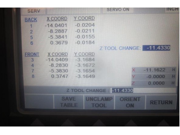
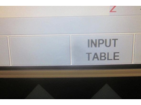
Go to service code 520. Press the "ATC front" then the "Go" key. Press the "Input table" key. Place a tool holder in any tool location. Use the hand wheel to jog X and Y to match the coordinating numbers for that location.
-
Use the hand wheel to highlight "Z tool change (height)." Press the "Orient On" key then the "Tool Unclamp" key. Air will purge through the spindle. Slowly lower the Z axis engaging the drive dogs in the tool holder until the air just stops. Raise the Z axis until it just starts.
-
Add -.010" to the Z number displayed in the DRO in the lower RH corner. Compare this to the number in the table. It should be very close. If needed, enter the new number in the keypad and press ABSet. Raise the Z axis. Press the "Return" key, Tool Unclamp",ATC back" then "Go." The ATC returns back.
-
Example" Z Tool Height displays -11.6500. After adding to the number it should read -11.6600. If you make any changes to the "Input table" press the "Save Table" key. Press the "Mode" key.
-
-
-
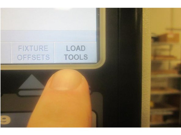
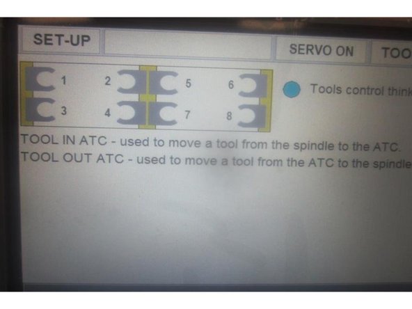
Go to "Set up, " then "Load Tools." Press "ATC forward" then "Go." Check all tool locations by loading and unloading a tool. Follow any prompts. Observe the Tool Grippers for smooth operation. Adjust if necessary.
-
Note: If the Tool Grippers are damaged, evaluate and replace if necessary.
-
Remove any tools from the process. Press the "Return" key twice. Press "Mode."
-
Almost done!
Finish Line


