-
-
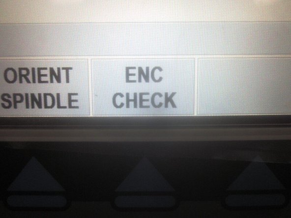
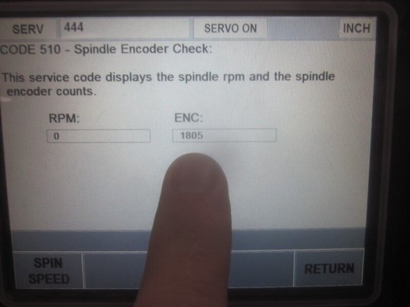
Perform this quick check to see if the encoder is counting. In Service Code 510 select the "Enc Check" soft key. Rotate the spindle by hand watching the screen. The small box on the right displays the encoder counting. If the numbers are NOT counting chances are the encoder is bad.
-
If the machine is experiencing spindle orientation faults or has trouble loading tools, this may also be a bad encoder.
-
Jog the X axis two inches to the LH side of center. Jog the Z axis so the spindle is about four to five inches from the table. Shut down the machine using the display panel (if possible) and disconnect the power at the main switch.
-
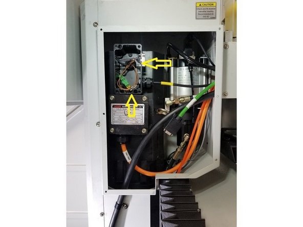
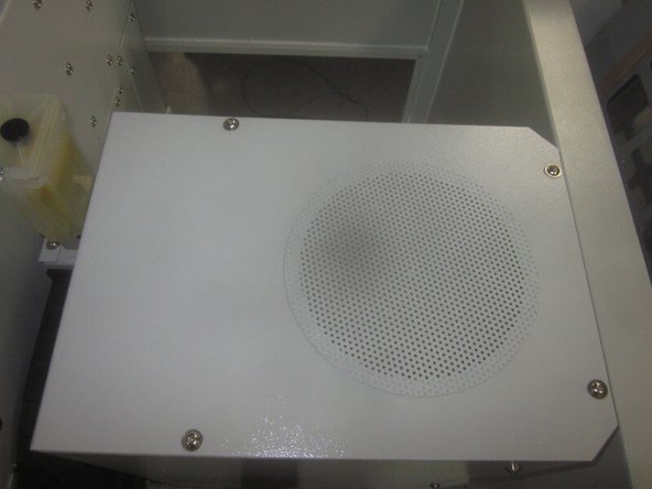
Remove the sheet metal cover on top of the spindle motor. Remove the sheet metal cover on the RH side of the spindle to gain access to the spindle motor wiring service boxes.
-
-
-
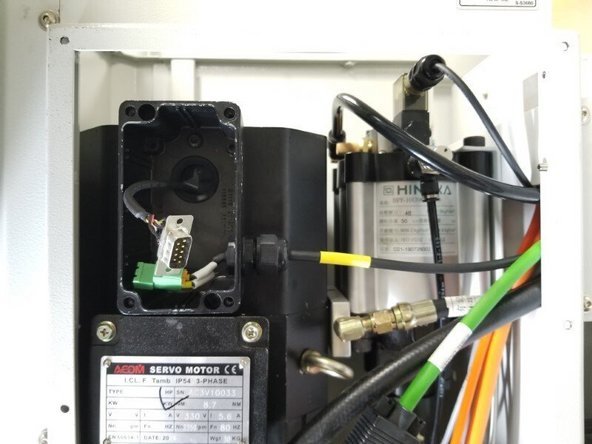
Remove the fan and encoder wiring service box cover on the RH side of the spindle motor. Locate the fan wiring connector (tan plastic) and disconnect the wiring.
-
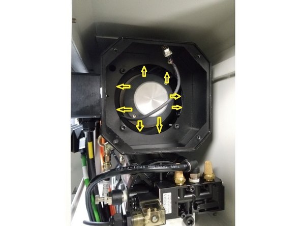
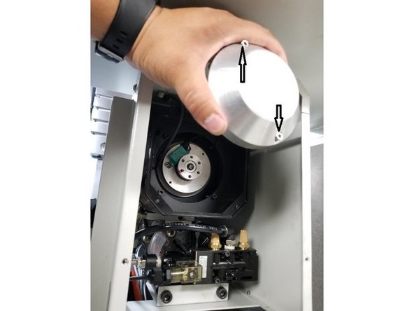
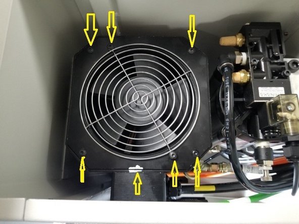
Mark the fan and the motor body to identify the orientation of the fan. Remove the four (4) 5mm BHCS attaching the fan to the top of the motor. Carefully lift off the fan. If the fan is stuck on, remove the two (2) 5mm BHCS with split washers separating the fan, grill and mounting plate.
-
Carefully feed the fan wires through the grommet and remove the fan. If you disassembled the fan to remove it, re-assemble it and set aside.
-
-
-
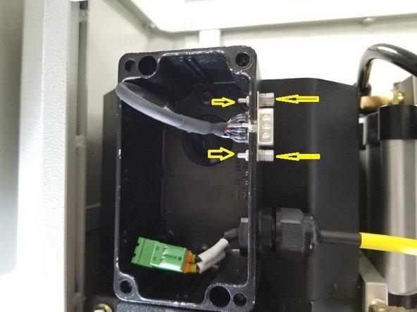
With a thin wall 5mm socket and 5mm wrench, remove the two (2) jack screws and nuts that fasten the DB9 connector to the service box. They are quite small so use care not to lose them.
-
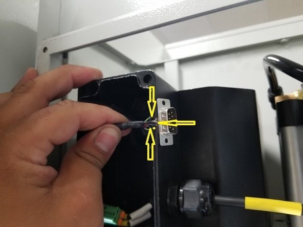
Before removing the plug, observe the orientation of it. There is a wire (ground) soldered in the middle of one outside edge. This wire must face towards the outside.
-
Carefully remove the encoder DB9 plug/cable assembly from the service box. Use care feeding it through the service box grommet as the wires are small and delicate.
-
-
-
After feeding the cable through the grommet, carefully unwind it from inside the motor. Original cables are about three (3) feet long and require a little patience to remove.
-
-
-
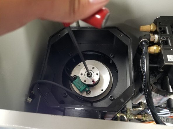
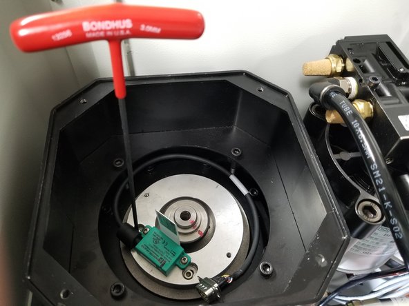
Use a 3mm long T-handle hex key or equivalent and loosen the two (2) 4mm SHCS that retain the (Encoder Housing Cover) until they are out of their threads. LEAVE THE SCREWS IN THE COVER to prevent them from dropping inside the motor.
-
Carefully lift the housing cover straight up and off out of the motor using care not to drop or lose hardware and set it aside.
-
-
-
Have a helper hold the drive dogs on the tool end of the spindle with a wrench to prevent rotation of the spindle shaft.
-
Use a 5mm long T-handle hex key or equivalent to remove the BHCS and washer from the end of the motor shaft.
-
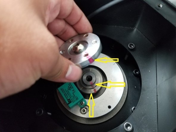
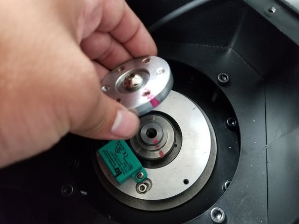
Before removing the balance ring, note it should be marked where it was originally placed for balancing. Carefully lift off the ring and look for the motor shaft and the encoder magnetic pick up ring to be marked as well. Use care during re-assembly to line up all the markings to retain motor balancing.
-
-
-
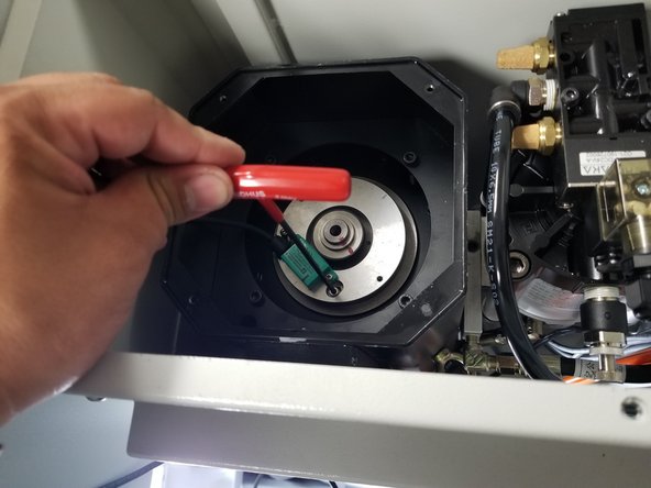
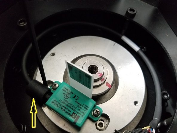
Use the same 3mm long T-handle hex key and carefully loosen the two (2) 4mm SHCS that fasten the Encoder Plate Assembly to the motor until they are out of their thread. Let them sit in their slots. DO NOT ATTEMPT TO REMOVE THE HARDWARE FROM THE PLATE ASSEMBLY. This reduces the chance of dropping hardware down in the motor.
-
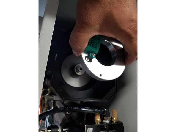
Very carefully lift out the Encoder Plate Assembly as a unit hardware and all and set aside.
-
Carefully avoid contact with the magnetic pick up ring.
-
-
-
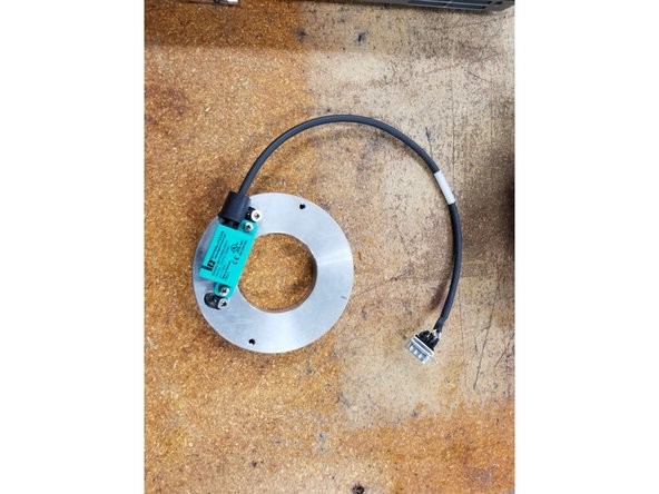
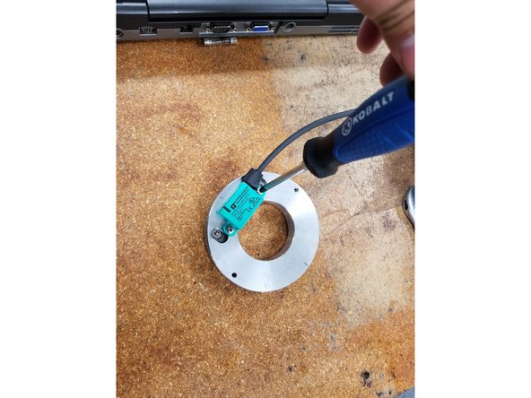
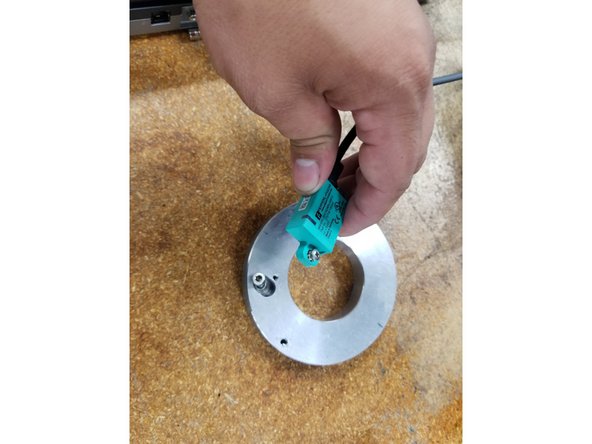
Place the Encoder Plate Assembly on a bench and carefully remove the encoder from the plate with a small cross tip screwdriver.
-
Install the new Encoder to the Plate and tighten the mounting screws securely.
-
-
-
Carefully place the Encoder Plate Assembly on the motor (avoid letting the Encoder contact the magnetic pick up ring) leaving some clearance. Snug up the 5mm SHCS.
-
Back off the mounting screws a bit so the Plate can move to adjust the clearance.
-
Place the plastic shim between the magnetic pick up ring and the Encoder. Set the clearance so the shim has a slight drag and can hold itself up without falling over.
-
Carefully place the balance ring on the motor shaft lining up the painted marks with the shaft. Install the washer and BHCS. Have a helper hold the drive dogs and tighten the screw securely.
-
-
-
Carefully replace the Encoder Housing Cover leaving the screws in the cover. Carefully fit the foam cable seal into the cover as you fit it. Tighten the screws securely.
-
Carefully fit the encoder cable through the grommet and attach to the service box using the same jack screws and nuts. Make sure the DB9 plug is mounted so the ground wire is mounted facing the outside.
-
-
-
Install the fan orientating it to your marks. If you didn't mark the fan, the wiring faces the RH side of the spindle. Feed the wiring through the grommet in the service box. Install the four (4) 5mm BHCS and tighten securely. Plug the fan wiring to the connector inside the service box.
-
Connect up the Encoder Cable to the DB9 plug and install the service box cover. Install the Top Sheetmetal cover to the spindle motor. Install the RH side sheet metal cover for the electrical service boxes.
-
-
-
Turn on the power at the main switch. Verify that the spindle motor fan is working.
-
Go to Service Code 510 and select "Enc Check."
-
Rotate the spindle and verify the Encoder is counting.
-
In Service Code 510, check and verify the spindle orientation angle. Adjust if necessary. After verification or any adjustments, go to Tool Loading and test load/unload several tool locations.
-