Tools
- Ladder to access the top of the machine
- 6 mm Metric deep hex socket
- 3/8 drive rachet and extensions
- 3/8 drive "wobble" extension 3 or 6 in long
- Small flat screwdriver
- Metric hex keys
- 3/16 inch hex socket or hex key
- 30-250 inch pound torque wrench
- 11/16 deep socket
- 12mm wrench
- special brake coupling nut puller
- Large 2 in cap. adjustable "crescent" wrench
- Large flat blade screwdriver
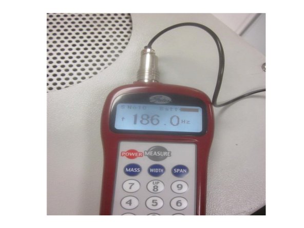
- Gates Sonic tension Meter 505C (optional)
Parts
No parts specified.
-
-
Remove any tooling fixtures from the table and tools from the spindle before starting work.
-
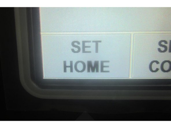
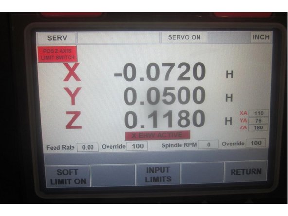
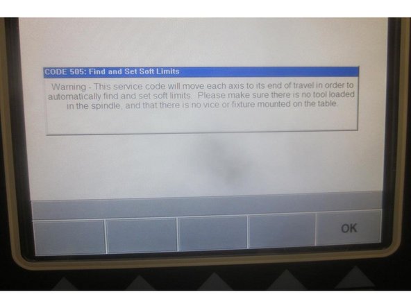
Start the machine and home it ( if possible ). If the Z axis faults, go to service code 505 and try to raise the Z axis. If it faults again, ask the operator or contact person if the Z axis was dropping. If the Z axis drops uncontrollably, the brake may have failed.
-
If the brake has failed, See the separate guide for replacing the Z axis brake. Use this guide in conjunction to replace or perform motor adjustments.
-
Caution: The X axis bridge must be supported if the brake has failed before attempting to replace the motor unless the bridge has bottomed out.
-
-
-
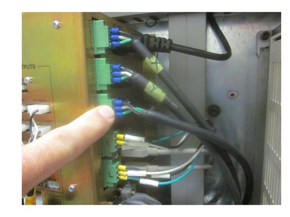
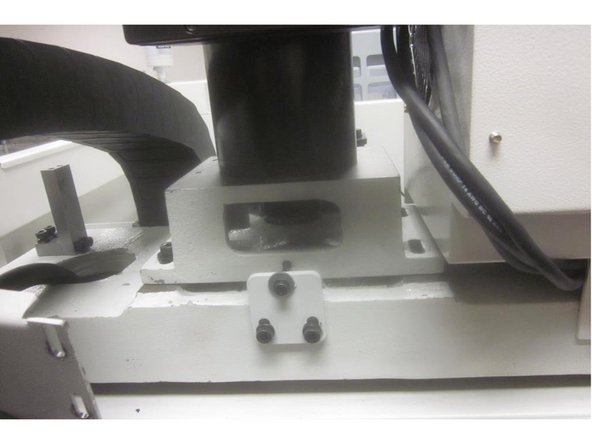
Shut down the machine at the main power disconnect switch. Remove the upper rear sheet metal panel to gain access to the motor wires routed in the column.
-
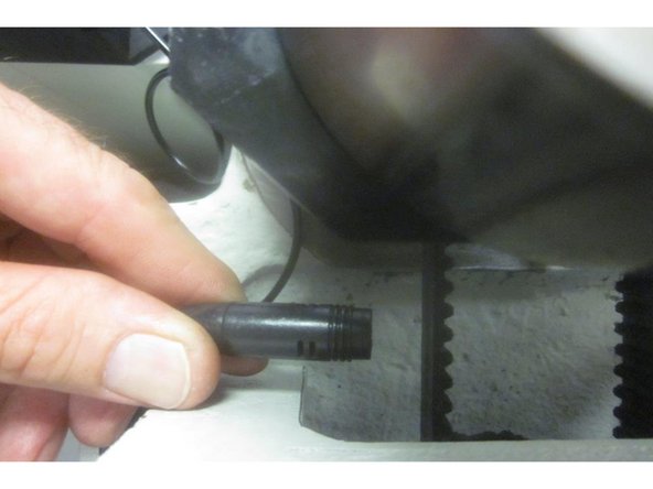
Disconnect the internal brake cable from the motor located inside the transformer box. Note: Some M 10's have the brake wire connector on the outside of the transformer box. If necessary, remove the top cover of the electrical transformer box to gain access to the connector.
-
-
-
Disconnect the power and encoder cables from the computer module inside the electrical panel.
-
Carefully remove the cables from the electrical panel up and out of the main column.
-
-
-
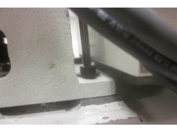
The X axis bridge must be supported ( unless it has bottomed out ).
-
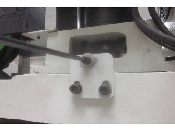
Remove the four (4) 8mm motor mount screws from the motor mount casting. Remove the 5mm belt tension screw from the rear base of the motor.
-
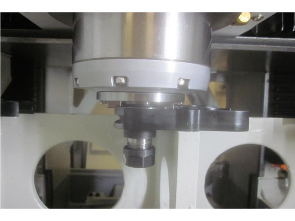
Slide the motor towards the front of the machine enough to remove the belt and carefully lift off the motor assembly.
-
-
-
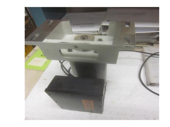
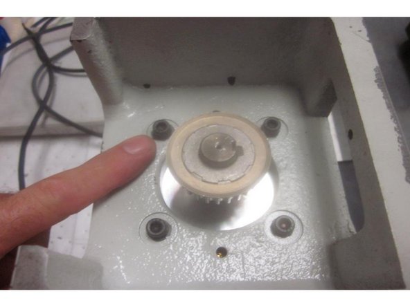
Carefully set the motor on a sturdy work surface with the cast mounting bracket facing up. Note the orientation of the bracket. The servo amp (box attached to motor) locates on the same side as the belt tension screw hole.
-
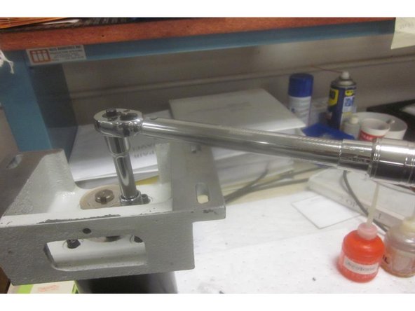
Using a 3/16 hex tool, remove the four (4) 1/4-20 SHCS that fasten the mounting bracket to the motor. These screws have Loctite on the threads. Use care removing them as the motor side thread is aluminum.
-
Clean any Loctite or debris from the screws. Swap over the mounting bracket to the new motor orientating the bracket as shown.
-
Install the screws and torque to 14 ft. lbs. ( 168 in. lbs.)
-
-
-
Insert wisdom here.
-
-
-
Insert wisdom here.
-
-
-
Insert wisdom here.
-
-
-
Insert wisdom here.
-