Tools
- Ladder to access the top of the machine
- 6 mm Metric deep hex socket
- 3/8 drive rachet and extensions
- 3/8 drive "wobble" extension 3 or 6 in long
- Small flat screwdriver
- Metric hex keys
- 3/16 inch hex socket or hex key
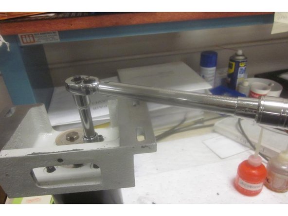
- 30-250 inch pound torque wrench
- 11/16 deep socket
- 12mm wrench
- special brake coupling nut puller
- Large 2 in cap. adjustable "crescent" wrench
- Large flat blade screwdriver
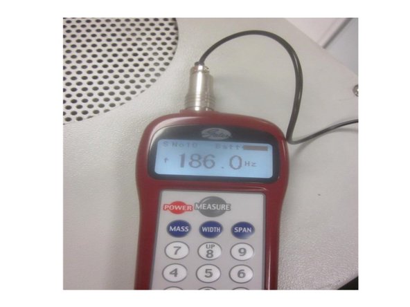
- Gates Sonic tension Meter 505C (optional)
Parts
No parts specified.
-
-
Remove any tooling fixtures from the table and tools from the spindle before starting work.
-
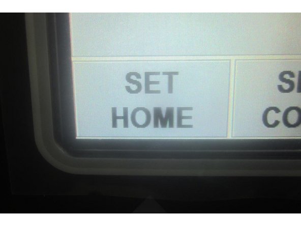
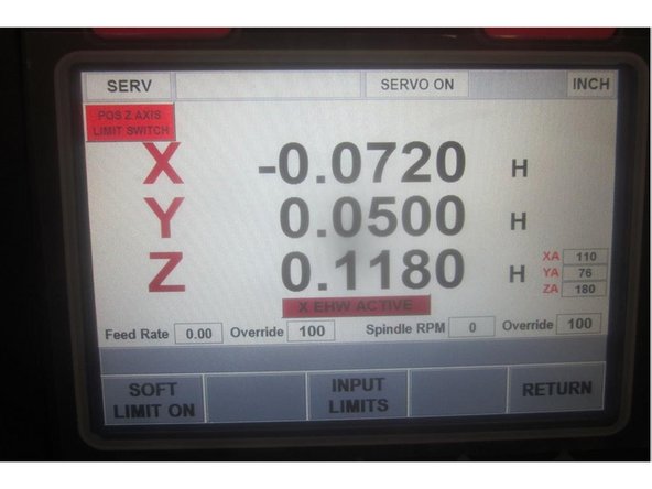
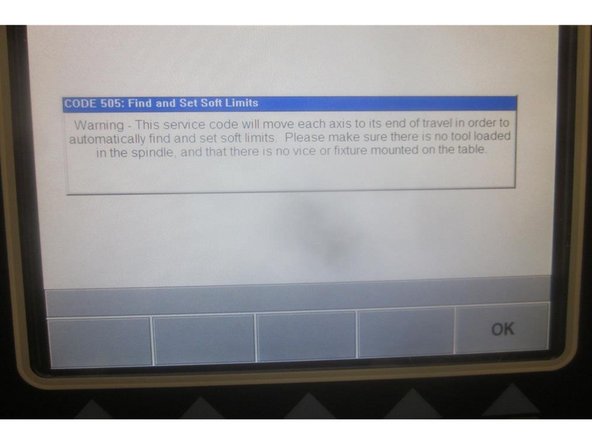
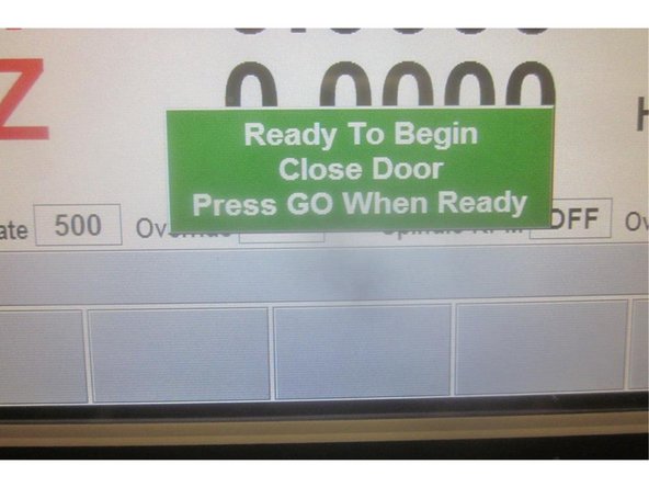
Start the machine and home it ( if possible ). If the Z axis faults, go to service code 505 and try to raise the Z axis. If it faults again, ask the operator or contact person if the Z axis was dropping. If the Z axis drops uncontrollably, the brake may have failed.
-
If the brake has failed, See the separate guide for replacing the Z axis brake. Use this guide in conjunction to replace or perform motor adjustments.
-
Caution: The X axis bridge must be supported if the brake has failed before attempting to replace the motor unless the bridge has bottomed out.
-
-
-
Shut down the machine at the main power disconnect switch. Remove the upper rear sheet metal panel to gain access to the motor wires routed in the column.
-
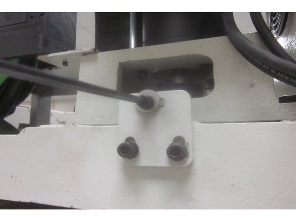
Disconnect the internal brake cable from the motor located inside the transformer box. Note: Some M 10's have the brake wire connector on the outside of the transformer box. If necessary, remove the top cover of the electrical transformer box to gain access to the connector.
-
-
-
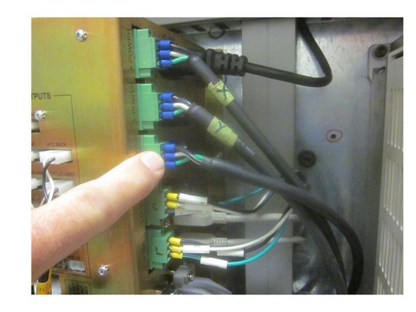
Disconnect the power and encoder cables from the computer module inside the electrical panel.
-
Carefully remove the cables from the electrical panel up and out of the main column.
-
-
-
The X axis bridge must be supported ( unless it has bottomed out ).
-
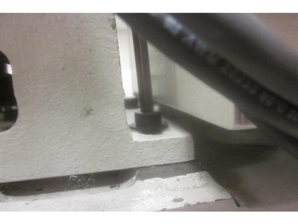
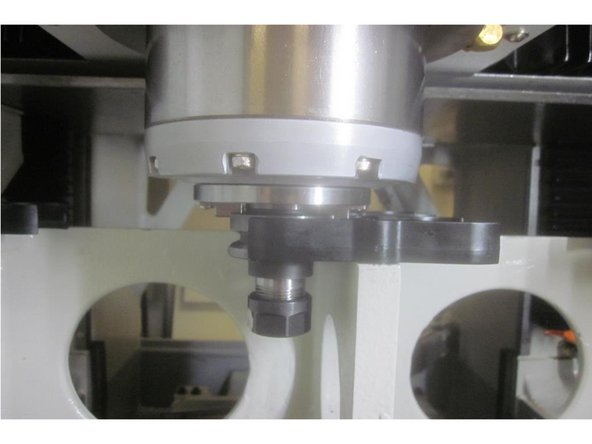
Remove the four (4) 8mm motor mount screws from the motor mount casting. Remove the 5mm belt tension screw from the rear base of the motor.
-
-
-
Insert wisdom here.
-
-
-
Insert wisdom here.
-
-
-
Insert wisdom here.
-
-
-
Insert wisdom here.
-
-
-
Insert wisdom here.
-