Tools
- Ladder to access the top of the machine
- 6 mm Metric deep hex socket
- 3/8 drive rachet and extensions
- 3/8 drive "wobble" extension 3 or 6 in long
- Small flat screwdriver
- Metric hex keys
- 3/16 inch hex socket or hex key
- 30-250 inch pound torque wrench
- 11/16 deep socket
- 12mm wrench
- special brake coupling nut puller
- Large 2 in cap. adjustable "crescent" wrench
- Large flat blade screwdriver
- Gates Sonic tension Meter 505C (optional)
Parts
No parts specified.
-
-
Remove any tooling fixtures from the table and tools from the spindle before starting work.
-
Start the machine and home it ( if possible ). If the Z axis faults, go to service code 505 and try to raise the Z axis. If it faults again, ask the operator or contact person if the Z axis was dropping. If the Z axis drops uncontrollably, the brake may have failed.
-
If the brake has failed, See the separate guide for replacing the Z axis brake. Use this guide in conjunction to replace or perform motor adjustments.
-
Caution: The X axis bridge must be supported if the brake has failed before attempting to replace the motor unless the bridge has bottomed out.
-
-
-
Shut down the machine at the main power disconnect switch. Remove the upper rear sheet metal panel to gain access to the motor wires routed in the column.
-
Disconnect the internal brake cable from the motor located inside the transformer box. Note: Some M 10's have the brake wire connector on the outside of the transformer box. If necessary, remove the top cover of the electrical transformer box to gain access to the connector.
-
-
-
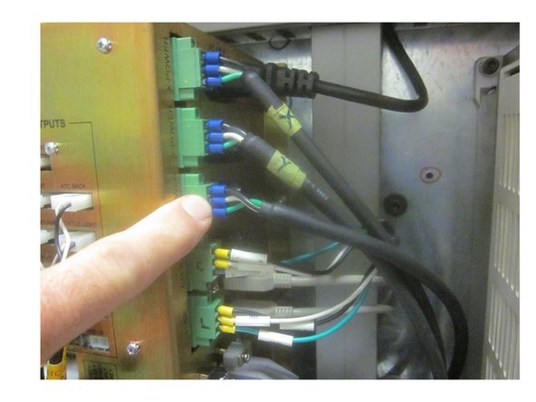
Disconnect the power and encoder cables from the computer module inside the electrical panel.
-
Carefully remove the cables from the electrical panel up and out of the main column.
-
-
-
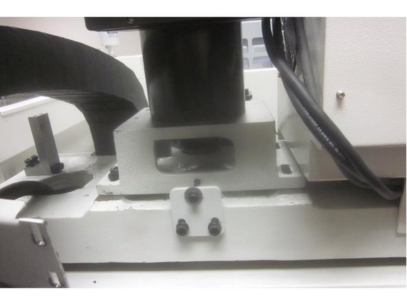
The X axis bridge must be supported ( unless it has bottomed out ).
-
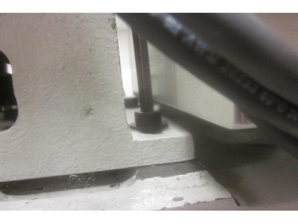
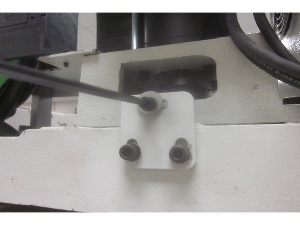
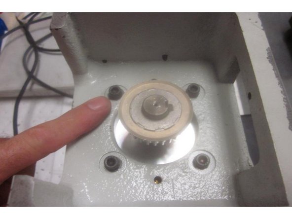
Remove the four (4) 8mm motor mount screws from the motor mount casting. Remove the 5mm belt tension screw from the rear base of the motor.
-
Slide the motor towards the front of the machine enough to remove the belt and carefully lift off the motor assembly.
-
-
-
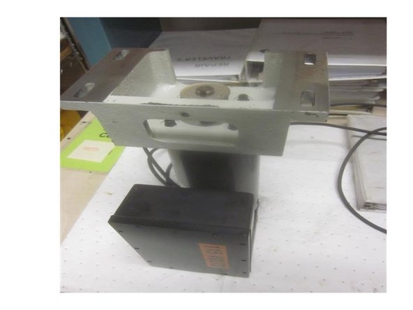
Carefully set the motor on a sturdy work surface with the cast mounting bracket facing up. Note the orientation of the bracket. The servo amp (box attached to motor) locates on the same side as the belt tension screw hole.
-
Using a 3/16 hex tool, remove the four (4) 1/4-20 SHCS that fasten the mounting bracket to the motor. These screws have Loctite on the threads. Use care removing them as the motor side thread is aluminum.
-
Clean any Loctite or debris from the screws. Swap over the mounting bracket to the new motor orientating the bracket as shown.
-
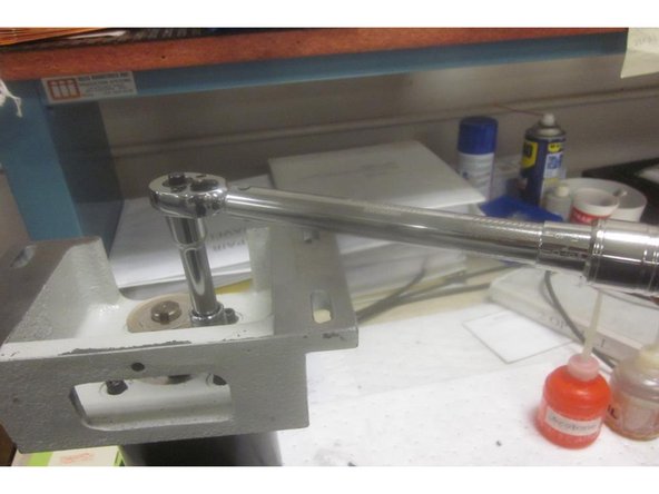
Install the screws and torque to 14 ft. lbs. ( 168 in. lbs.)
-
-
-
Check the mounting surfaces of both the machine and the motor mounting bracket for dirt, debris or burrs. Clean up as necessary. Lubricate all fasteners prior to installation.
-
Carefully lift the motor and set it on the mounting surface of the column. Install the belt, tension screw and the LH mounting screws only.
-
Route the cables back through the RH side of the column and re-connect them. Tighten the belt tension snug enough to jog the axis . Tighten the LH mounting screws securely.
-
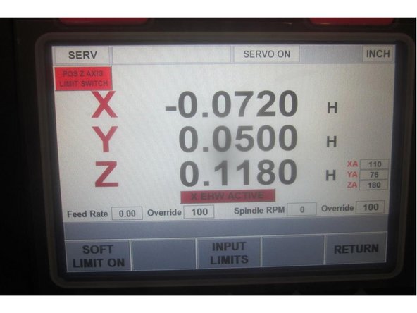
Start up the machine and home it. Go to service code 505, carefully raise the Z axis until the limit switch lights and check the index angle. Note the number displayed.
-
Lower the Z axis to the number noted leaving enough room to access the motor and belt assembly.
-
-
-
After noting the index angle, disconnect the Z brake wire from the computer module. This will hold the X axis bridge from dropping.
-
Remove the LH motor mounting screws. Remove the belt tension screw. Slide the motor forward and remove the belt.
-
In service code 505, Use the hand wheel to adjust the Z index angle to 180 deg. Install the belt, tension screw and all the mounting screws. Adjust the tension on the belt enough to only allow it to turn 45 deg.
-
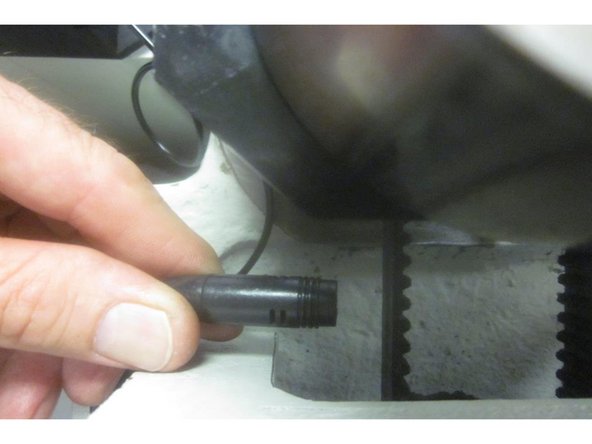
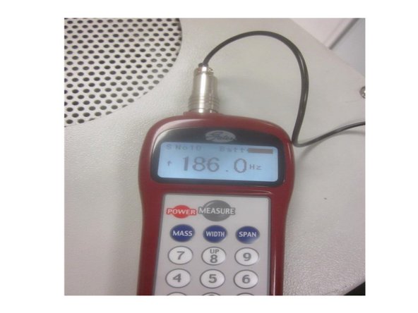
If using the Gates Sonic Tension Meter 507C under test "S 10," adjust the tension to 185-200 HZ. Hold the gauge probe about 3/8" from the belt. Pluck the belt ( like a guitar string ) and check the meter. Adjust belt tension up or down to meet the specification.
-
Tighten all the mounting screws securely. Re-connect the Z brake wire. Home the machine again. Go to service code 505 and check the Z axis index angle. If still out of spec, repeat the previous steps until in spec 180 + or - 45 ( 135-225).
-
-
-
Go to service code 520. Press the "ATC front" key and the ATC jogs forward. Press the "Input Table" key. Highlight the Z height with the hand wheel and note the number in DRO on the RH lower corner.
-
Place a tool holder in any ATC tool location. Move X and Y to match the coordinating numbers in the Input Table location. Press the "Orient" key then the "Tool Unclamp" key. Air will purge out through the bottom of the spindle.
-
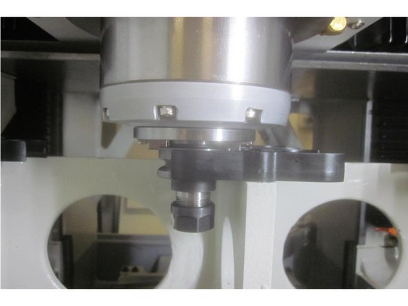
Slowly lower the Z axis until the drive dogs engage and the air from the spindle just stops. Slowly raise the Z axis until the air just starts. Note the number for Z in the DRO display. Add -.010" to this number, enter it with the key pad and press ABSet. Press the "Save Table " key.
-
Example: Z Tool Height displays -11.6500. After adding to the number it should read -11.6600.
-
Raise the Z axis to clear the tool. Press the "Tool Unclamp" key again. Go to Tool Loading. Check loading and unloading the tool. Check all tool locations watching for excess flexing of the tool grippers. Adjust the Z height if necessary to obtain smooth operation. Note: Damaged tool grippers can cause excess movement during loading and unloading.
-
If tool grippers are damaged, inspect and replace them if necessary.
-
-
-
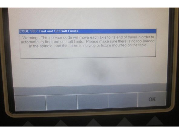
"Caution: Make sure there are no fixtures on the table or tools in the spindle.'
-
Go to service code 505. Select the "Set Soft Limits" key. A blue warning appears repeating the "caution" mentioned above.
-
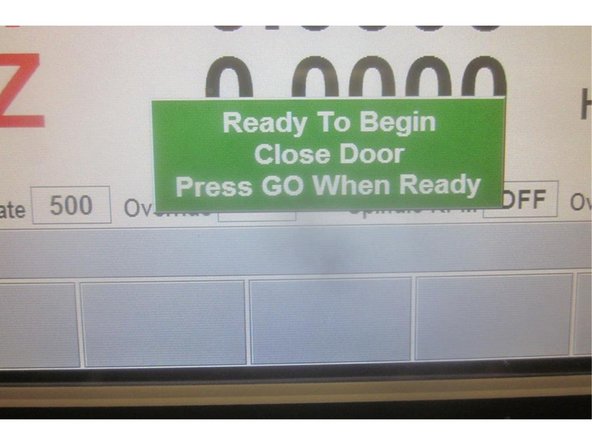
Press "OK." Now press "Go." The machine will rapid travel through all axis to set the limits. When finished it will return to 505.
-
Mode out.
-


