Tools
- Special puller for brake bushing P/N 28203
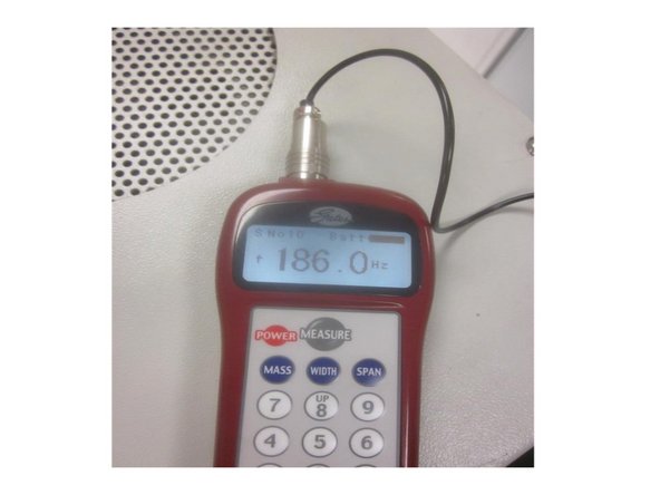
- Optional Gates Sonic tension Meter 507C
- 4, 5 and 6 mm depp ball drive hex sockets
- Metric hex keys
- Large 2 in cap. adjustable "crescent" wrench or 1 1/16" wrench
- Large flat blade screwdriver
- 11/16 deep socket
- 3/8 drive rachet and extensions and adapters
- Six foor ladder or step stool
Parts
No parts specified.
-
-
Remove any tooling fixtures from the table and tools from the spindle before starting work.
-
Remove the rear upper sheet metal panel behind the Z axis motor and set aside.
-
Power up the machine and home it. If the Z axis attempts to home and drops by itself or if the E-stop button is pressed with the axis raised and it drops, there is good chance the brake has failed.
-
-
-
If the Z axis is raised you must support it with lumber or other suitable material to prevent it from dropping.
-
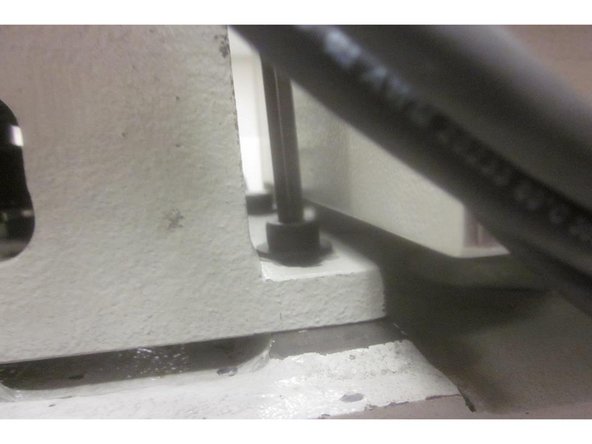
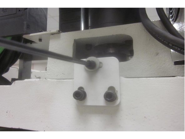
If the Z axis is bottomed out in travel leave the power off. Remove the four (4) motor mount bracket screws and the belt tension screw. Slide the motor forward and remove the belt from the pulley. Replace one mounting screw to secure the motor from toppling over.
-
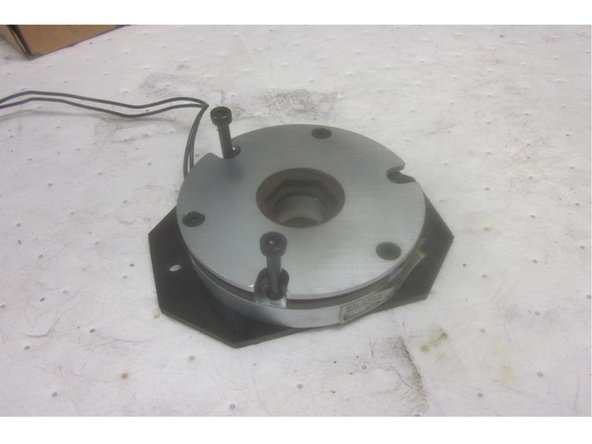
Remove the brake cover, spacers and the two (2)brake cover screws of three that fasten the brake to it's mounting plate. Note their orientation and the location of the brake wire ( LH rear of machine). Disconnect the brake wire.
-
Use the wrench "flats" below the casting for the upper bearing housing to hold the ball screw. Remove the 11/16" nut, star washer and flat washer. Remove the screw securing the brake to the mounting plate. Lift off the brake assembly with the hex shaped "coupling bushing".
-
If the coupling bushing is stuck on, remove the plate mounting screws. Rotate the plate / brake assembly until you can access the stand offs and remove them. Carefully install the "special puller" and remove the the coupling bushing.
-
Lift off the brake / plate assembly.
-
-
-
Attach the brake to the mounting plate in the correct orientation allowing the installation of the brake cover. Use the cover screws to align the brake to the plate.
-
Place the assembly over the ball screw. Install the coupling bushing. Note: The bushing should be a "slip fit" onto the ball screw. If you used a puller to remove it, there might be a burr or nick that's easily cleaned up to correct this. Install the flat washer, star washer, nut and tighten securely. Do not force the bushing on.
-
Install the stand offs ( if removed). Lift up on the brake rotating it to fit the disc into the coupling bushing at the same time lining the plate up on the stand offs. Install the screws and tighten securely.
-
If the brake disc won't align: Power up the machine. Connect the brake wire ( this will allow the disc to float and align with the bushing ) and repeat the above step.
-
-
-
With the power on and servos energized, re-install the belt on the motor pulley . Install the tension screw and the motor mounting screws. Adjust the belt tension and tighten the mounting screws.
-
Go to service code 203 and home the machine.
-
-
-
Machine must be homed to proceed. Go to service code 505. Raise the Z index slowly until the limit switch lights. Note the index angle number.
-
If the index angle is out of spec ( 180 + or - 45 135-225 ), lower the Z axis enough to gain access to the Z motor mounting area. Stop at the number shown when the limit switch lit up. Disconnect the Z axis brake wire at the computer module. This will hold the bridge from dropping.
-
Remove the motor mounting screws and the belt tension screw. Slide the motor forward to remove the belt. Rotate the hand wheel to reach 180 deg. and re-install the belt, tension screw and the mounting screws. Set the belt tension and tighten the motor mounting screws securely.
-
If using the Gates Sonic Tension Meter 507C, set the belt tension in test "S 10" to 185-200 HZ. Hold the meter probe approximately 3/8" from the belt. Pluck the belt ( like a guitar string) to test.
-
Home the machine again. Go to service code 505 and check the index angle again. Repeat the step if necessary.
-
-
-
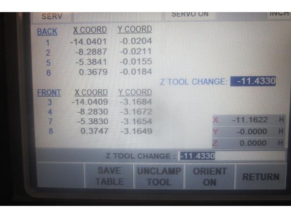
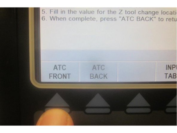
Go to service code 520. Press the "ATC front" key, "Go" key then the "Input table" key. The ATC comes forward and the tool locations are displayed. Use the hand wheel to highlight the Z Tool Change. Note the DRO display in the lower RH corner.
-
Place a tool holder in any of the tool locations. Jog X and Y to match the coordinating numbers for the selected tool location. Press the "Orient on" key. The spindle will orient to load a tool.
-
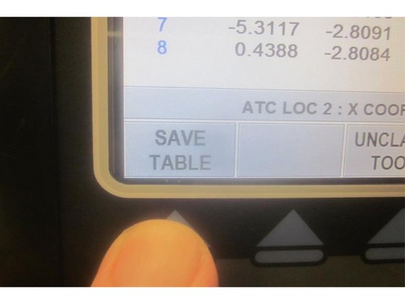
Press the " Unclamp Tool " key. Air will purge through the spindle. Slowly lower the Z axis until the air just stops then slowly raise it until the air just starts. Note the number for Z in the DRO display. Add (-) .010" to it and enter this number in the display then press ABSet. Press the "Save table " key.
-
Raise the Z axis to clear the tool holder. Press the "ATC back" then the "Go" key. The ATC returns back inside. Go to "Tool loading" to load and unload the tool holder. Observe the tool grippers for deflection. Adjust the Z height if necessary to obtain smooth action.
-
It's good practice to check all tool locations. If you change the Z tool height press the "Save table" key to save your changes. Press the "Return" key and mode out.
-
-
-
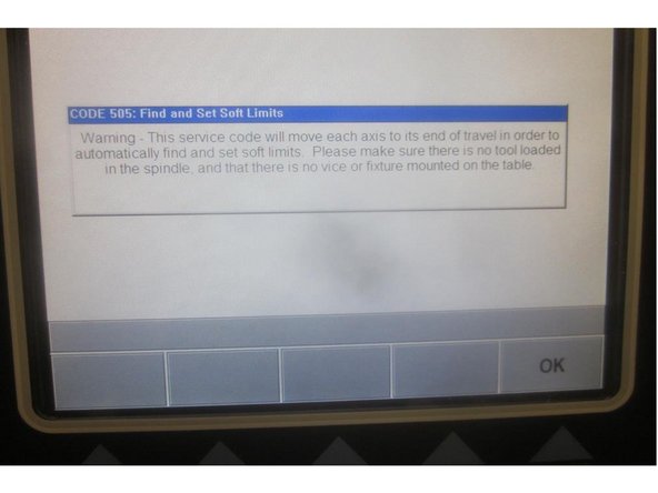
Caution: Remove all tooling from the table and the spindle before setting soft limits.
-
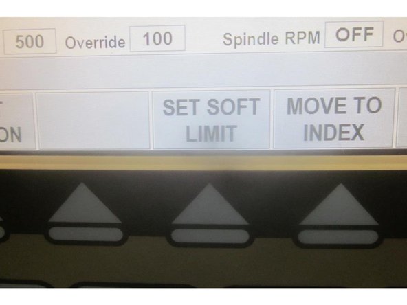
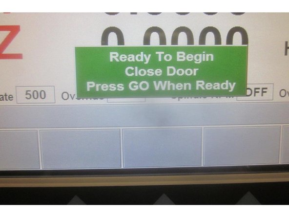
Go to service code 505. Press the "Set Soft Limits" key. A blue warning appears reminding of the caution above. Press "Ok" the "Go" and the machine will rapid all axis to set the limits. When finished it will be in Service code 505.
-
"Mode " out and shut down the machine.
-


