Tools
- Metric hex keys
- 3/8 drive rachet and extensions
- 3/8 drive "wobble" extension
- 1/4 drive metric hex sockets
- Large 2 in cap. adjustable "crescent" wrench or 1 1/16" wrench
- 1 1/2 (39mm) inch "crownfoot" wrench
- 0-100 ft./lbs. torque wrench
- 30-250 in. lbs. torque meter
- extendable magnet
- metric combination wrenches
- SWI 2 OP maintenance Manual
- 4 foot or 6 foot ladder
- "short" 1 inch long x 1 inch long 3 mm hex key
- 4x4x10in wood block
- 4x4x13 in wood block
- 4x4x17 in. wood block
- 1/4 in. by 4 in. brass drift
- 1 1/4 inch (32mm) "crowsfoot" wrench
- Special puller for brake bushing P/N 28203
Parts
No parts specified.
-
-
Steps of this guide require you to work on the machine powered up. Use caution when doing so. Use the E-stop if you can. Remove any tooling fixtures from the table and tools from the spindle before starting work.
-
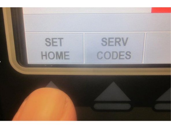
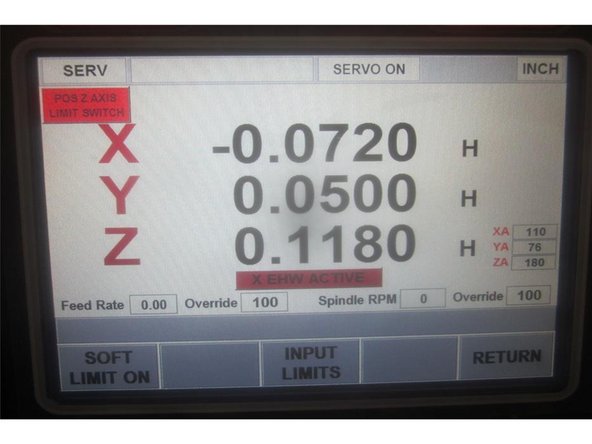
If possible, power up the machine and "home" it. If you cannot home the machine, use service code 505 to jog the axis.
-
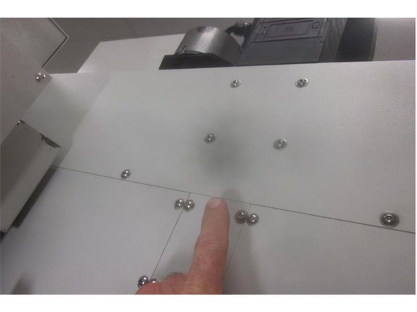
Remove the LH and RH sheet metal panels. Remove the upper sheet metal panel located behind the spindle motor. It may be necessary to loosen other screws and components in this area to ease access to the ball screw. Remove the upper cushion and spacer from the ball nut.
-
Raise the Z axis, disconnect the air and remove the ATC door. Disconnect the air cylinder at the pivot bolt. Remove the four (4) screws that attach the door to the column.
-
Jog the Z axis up and down to access the ball screw cover screws. There are four (4) vertical that attach the cover at the top, six (6) horizontal that attach the cover frame to the column and two (2) vertical that attach at the bottom of the lower bearing housing.
-
Tip: Using a shortened 3mm hex key for the column screws eases the job. Gain access to the middle and upper column screws from the top.
-
Once loose ( the Z axis at the top ), slowly slide down and remove the cover as an assembly. Remove the lower cushion and spacer from the bearing housing.
-
-
-
Raise the Z axis to allow access to the ball screw.
-
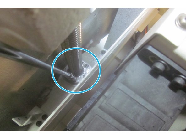
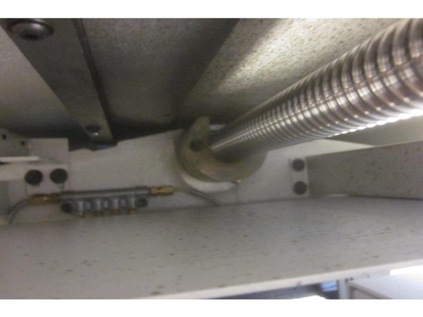
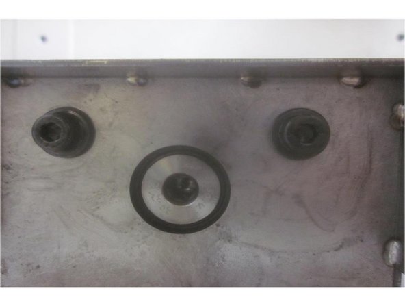
Disconnect the oil line that feeds the ball screw. Rotate the ball screw and loosen the three (3) set screws that secure the lower lock ring nut. Using the piece of brass or aluminum stock, tap on the set screws to loosen the inserts underneath and remove the lock ring nut.
-
Lower the Z axis so you have access to the top and bottom.
-
Support the bridge with lumber or other suitable material to prevent it from dropping.
-
Shut down the 2 OP and shut off the power at the main disconnect switch.
-
-
-
Remove the upper and middle rear sheet metal panels for access. Remove the four (4) motor mount screws and the small tension screw from the motor mount casting. Remove the belt from the motor pulley. Replace one motor mounting bolt and snug it up to prevent the motor from toppling over.
-
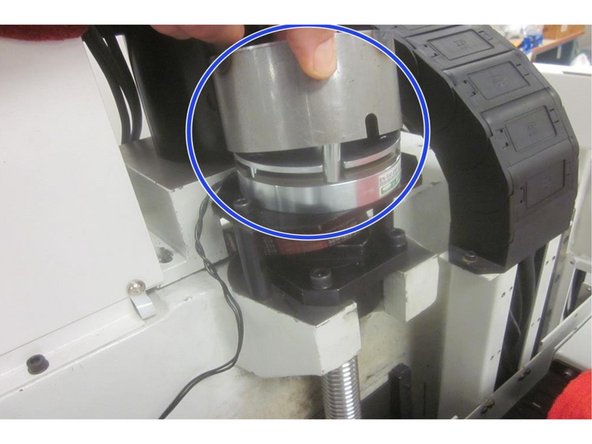
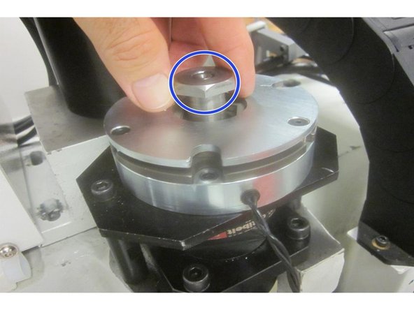
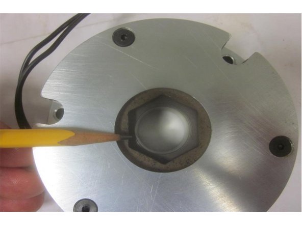
Remove the brake cover. Disconnect the brake wire. Remove brake plate mounting screws and standoffs. Remove the nut, lock washer and coupling bushing. Remove the brake assembly and belt.
-
On occasion the coupling bushing is stuck on the ball screw. After the stand offs are removed, this allows the brake / plate assembly to drop a bit. Use puller P/N 28203 to remove the coupling bushing avoiding damage.
-
Remove the three (3) screws that attach the ball nut to the yoke. Remove the four (4) screws attaching the upper bearing housing to the column.
-
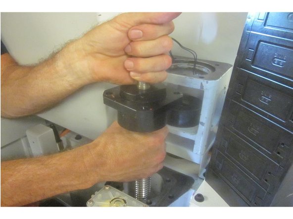
Once free, lift the ball screw up and out from the machine.
-
Note: Some early M 10's have a thicker spacer under the upper cushion and the cushion is slightly different than current models. If the cushion needs replacement, contact SWI for assistance.
-
-
-
It's recommended to replace all bearings when replacing a ball screw. Clean all related parts for the job including any "machined" contact areas.
-
With the ball screw removed from the machine, lay it on a flat surface.
-
Remove the locknut, star washer, flat washer, sprocket, ferrule and key. Loosen the 10-32 lock screw on the bearing clamp nut. Remove the clamp nut from the ball screw and slide off the bearing housing.
-
-
-
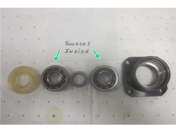
Lube all fasteners prior to installation. Inspect the new ball screw for damage. Position the ball nut in approximately the same place as the old one. If replacing the upper angular contact bearings (recommended), make sure they are greased and orientated correctly with the spacer in between and install the outer seal open side out.
-
Note: The Angular Contact Bearing narrow inner race should face towards the inside spacer. Bearings should face each other.
-
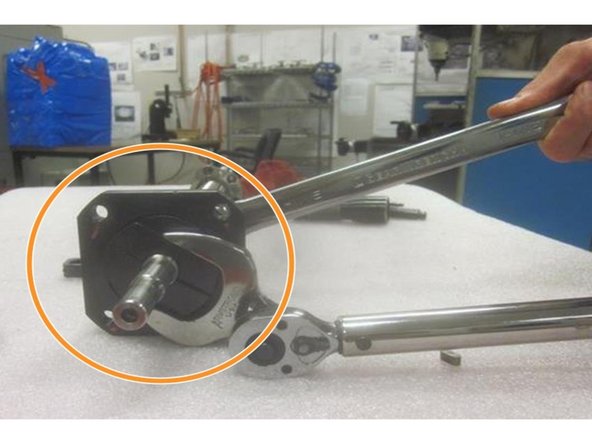
Carefully fit the assembled upper bearing housing onto the end of the ball screw. Lube the threads and install the clamp nut. Torque it to 50 ft. lbs. and the lock screw to 60 in. lbs. Install the lower bearing. It is a precision fit and may require a light "tap" to seat it against the shoulder on the ball screw.
-
Install the woodruff key, ferrule, sprocket, flat washer, star washer and nut. Tighten securely. Note: This can performed later if necessary.
-
Carefully slide the ball screw into position. Rotate the ball nut until it contacts the yoke casting. Position it so the hole for the oil line is facing the LH side of the machine. Install the oil line. Turn the ball nut so the curved edge faces forward and the oil line is at 4 o'clock.
-
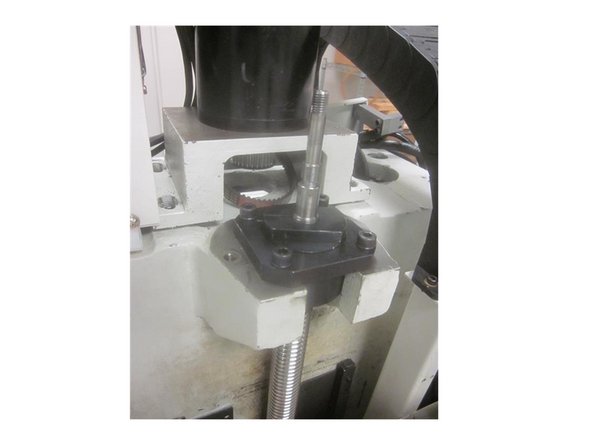
Install the upper bearing housing screws and the three ( 3) ball nut screws ( just taking up most of the thread ). Torque the upper bearing housing screws to 18 ft. lbs. Install the lower bearing ring nut and tighten the set screws.
-
-
-
If not completed, install the belt sprocket and related hardware mentioned in step 5. Install the stand offs. Install the belt. Leave the belt off the motor. Leave off the brake cover. Place the brake / plate assembly on between the standoffs. Install the coupling bushing, washer, star nut and lock nut.
-
Carefully line up the brake so the hex in the friction disc fits in the "coupling bushing." Lift up and turn the brake so the hex engages the coupling bushing. Rotate it to line up the mounting holes in the plate with the stand offs and install the screws. Re-connect the brake wire.
-
If the hex in the brake disc won't align, power up the machine and press the servo button. This will release the disc allowing it to "float" and assist alignment. Finish installing the brake assembly.
-
Install the belt on the motor, set the tension and tighten the mounting screws securely.
-
Using service code 505, jog the Z axis as low as possible and still have access to the lower bearing housing. Break loose the housing screws allowing the housing to "float" then torque to 18 ft. lbs.
-
-
-
Warning: This step requires working on the machine with the power on. In this step use caution and have the proper sizes of lumber or other suitable material to support the bridge.
-
Power up the machine and home it. Go to service code 505. Adjust the Z axis near the top leaving access to the ball nut screws. Torque the screws to 84 in. lbs. in a star pattern. Install the upper cushion spacer and torque the screws to the same spec. Install the cushion and "snug" up these screws. Support the bridge to prevent it from dropping.
-
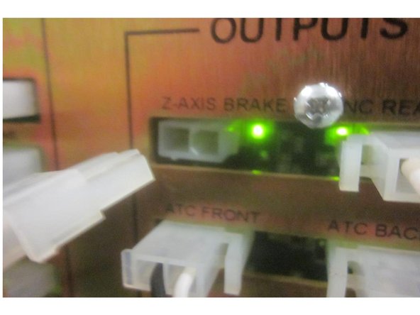
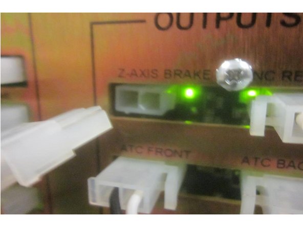
Connect the special brake switch to the 115 volt connection in the electrical cabinet. The small white 2 (two) wire connector attaches to the Z axis brake wire from the computer module. When you disconnect the wire from the computer there is a "click" sound. This indicates power "off" to the brake.
-
Connect the switch. If you hear the "click" again, then power is restored to the brake. If not,toggle it to activate the power. Power to the brake must be "on" to check the rolling torque. The bridge must be supported any time power to the brake is applied.
-
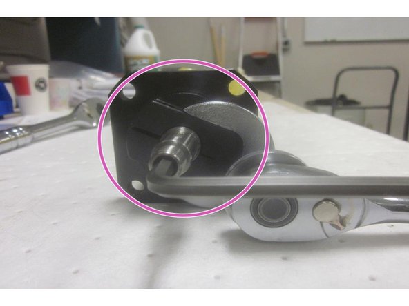
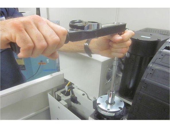
Using a 13/16" socket, a proper length extension and torque meter, check the rolling torque of the Z axis. Rotate the ball screw counter clockwise "up" to check. Repeat this process at the middle and bottom of the axis travel ( three (3) places).
-
Rolling torque spec is 25 in. lbs. + or - 5 in. lbs.
-
Double check that all fasteners are tight and properly torqued.
-
Raise the Z axis and remove any supports. Press the E-stop button.
-
-
-
'''Use caution if you work on the machine with the power on. Use the E-stop when you can'''
-
Install the Z axis brake cover. Install the spacer and cushion on the lower bearing housing. Install the Z axis ball screw cover. Lube all fasteners. Start the bottom screws in the lower bearing housing then start the rest. Starting at the top working down, tighten all the screws securely. Install the ATC door.
-
Connect the air. Jog the Z axis up and down and check for any binding of the ball screw cover.
-
Install the upper sheet metal panel above the rear of the spindle. Install the X axis upper and lower side covers to the bridge. Check any "other " screws or components that were loosened for access to the ball screw.
-
-
-
Use caution if working on the machine with the power on.
-
Power up the machine and "home" it first before attempting to set the index angle.
-
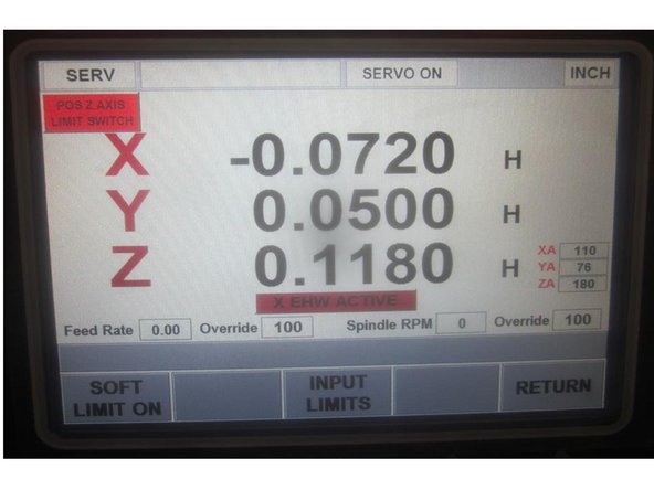
Under power in service code 505, raise the Z axis near the limit switch. Using the .0002" resolution, raise Z until the limit switch lights. Note the index angle number. If the number is within spec ( 180 + or - 45 (135-225) proceed to step 10. If the number is out of spec adjust the index angle.
-
Raise the Z axis until the soft limit switch lights. If out of spec, lower the axis to that number allowing access to the motor/belt area.
-
Disconnect the Z brake wire at the computer module. Note: This will hold the bridge from dropping.
-
Remove the motor mount and tension screws. Slide the motor forward removing the belt from the pulley . Use the hand wheel to rotate the motor to 180 deg. Re-install the belt and all the screws. Set the belt tension and tighten the mounting screws securely. Home the machine. Re-check the index angle.
-
-
-
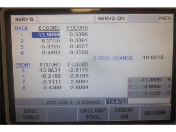
Go to service code 520. Press the "ATC front" key, then "Go" to bring the ATC forward. Press the "Input table" key.
-
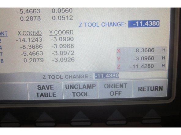
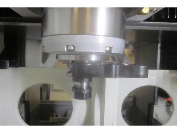
Using the hand wheel, highlight the "Z Tool Change" number. Place a tool holder in any location. Jog X and Y to match the assigned tool location numbers. Press the "Orient on" key. Press the "Unclamp tool" key. Slowly lower the Z axis engaging the drive dogs until the air from the spindle just stops. Raise it until it just starts.
-
Note the number displayed in "Z" in the DRO in the lower right corner of the screen. Add (-) .010" to this number, enter it in the display and press ABSet. Press the "Save Table" key. Raise the Z axis to clear the ATC.
-
Example: Z Tool Height displays -11.5500. After adding number should read -11.5600. Press the "Save Table" soft Key.
-
Remove the tool from the ATC. Press the " Return" key, "ATC back", "Go" then the "Return" key. Enter service code 203 and "Home" the machine.
-
Check the Z height by loading and unloading several tool locations in the "Tool Loading" process. Look for deflection of the tool grippers during the process. Adjust the Z tool height as necessary to obtain smooth operation.
-
Go to service code 300. Cycle the lube pump several times to ensure the ball screw has oil circulating through it.
-
-
-
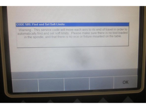
Caution: Remove all tooling or fixtures from the table and spindle before setting soft limits.
-
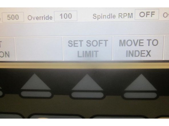
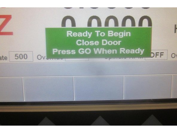
Go to service code 505. Press the "Set Soft Limits" key. A blue warning appears reminding of the above "caution." Press "OK" the "Go." The machine will rapid all axis to set the limits. When finished it will be in 505. Mode out.
-
Install any remaining sheet metal panels.
-


