Tools
- Six foot ladder
- Co-axial indicator with .375" pilot
- BT30 Tool holder with .375" female collet
- 1 BT30 tool holder with clamping journal
- Metric hex keys
- 4,5,6mm 1/4 drive metric sockets
- 3/8 drive rachet with extensions
- "short" 1 inch long x 1 inch long 3 mm hex key
- 3/16 inch hex socket
- 10-200 inch lbs Torque Wrench
- Small flat blade screwdriver
- metric combination wrenches
- 1/4 drive racket and extensions
Parts
No parts specified.
-
-
Power up the machine and home it. Jog the Z axis to full up position. Remove the ATC door by disconnecting it at the air cylinder pivot bolt. Remove the four (4) screws attaching it to the column.
-
Remove the outside left and right side covers from the machine. Remove the upper sheet metal panel behind the spindle.
-
-
-
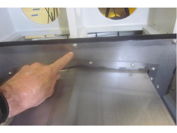
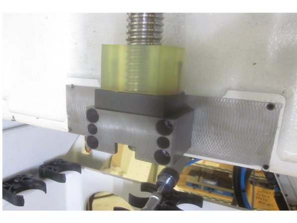
Remove the Z axis ball screw cover. Remove the twelve screws attaching the cover. Six (6) vertical 5mm( four at the top and two under the lower bearing housing) and Six (6) 5mm horizontal to the column.
-
Remove the sheet metal panel above and behind the spindle allowing easier access to the upper screws. A short 1" x 1" 3mm hex key eases the job removing the horizontal screws. Remove the bottom screws in the lower bearing housing last.
-
Raise the Z axis and continue to remove the rest of the screws. Once loose, slowly slide out the cover from the bottom and set aside. Remove the ball screw cushion and spacer from the lower bearing housing.
-
-
-
Jog the table to the front of the machine using the Y axis.
-
Disconnect the air from the machine.
-
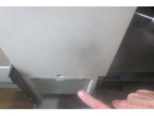
Remove the lower sheet metal panel and seal attached to the botom of the ATC. Manually remove any tools loaded in the ATC.
-
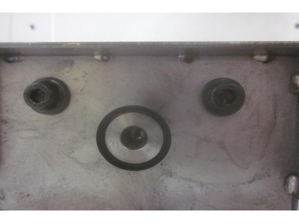
Slide the ATC forward and remove the four (4) 8mm SHCS that attach the tool magazine to the carriages. Lift off the tool magazine and push back the lower tool carriages. Do not lose the ring shaped "locating pin" part number 28043.
-
Go to service code 505. Jog the Z axis down far enough to access the motor cavity ( located in the lower column in the rear side of the machine ). Make sure the ball nut doesn't hit the lower bearing housing. Press the E-stop.
-
-
-
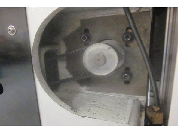
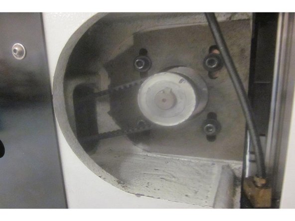
Remove the four ( 4 ) 1/4-20 SHCS attaching the motor to the casting. Remove the long 8mm belt tension adjustment screw from underneath the casting. The motor will be resting on the casting. Remove the belt from the pulley.
-
With the Z axis low enough to access the X motor cavity, remove the rear lower sheet metal access panel. Press the E-stop button. Power down the machine.
-
From the back of the machine disconnect the encoder cable and power cable from the motor. Slide the motor to the right while rotating it (towards you) in a forward direction carefully removing it from the machine.
-
-
-
With the servo drive (box attached to the motor) facing the rear of the machine, lift the motor while rotating the servo box downward into the X axis cavity at the rear of the machine. The servo housing faces down when the motor is installed. Start the 1/4-20 screws.
-
Install the belt on the motor. Connect the encoder and power cables. Install the long 8mm belt tension screw. Adjust the tension so the belt will only turn 45 deg. Tighten up the 1/4-20 screws. Release the E-stop.
-
Install the X motor lower sheet metal panel. Power up the machine.
-
-
-
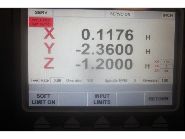
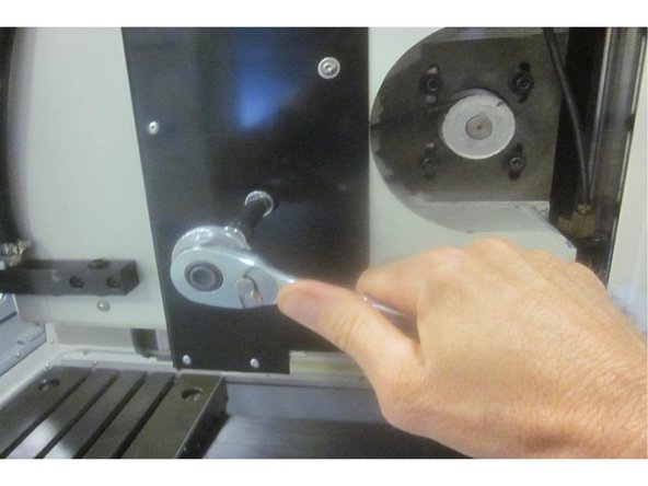
Go to service code 203 and home the machine. Go to service code 505 and slowly jog the X axis to the far right side to light the limit switch. Note the index angle number. Press the E-stop. Rotate the ball screw manually until it touches the cushion and relaxes.
-
Back off the ball screw exactly one full turn. Release the E-stop. Press the servo button. Go to service code 505. The limit switch for X should be lit. Note the index angle for X on the display. Adjust the cam if necessary so the switch lights one full turn from the bumper. Loosen the adjusting screws, lower the motor and remove the belt.
-
Use the hand wheel to adjust the index angle to 180 deg if necessary. Re-install the belt, adjust the tension and tighten up the motor screws. Jog the axis and check again. Go to service code 203 and home the machine. Go back to service code 505 and check the index angle again,
-
We are looking for 180 deg. + or - 45 deg. If not within this spec adjust the index angle as necessary.
-
-
-
Install the Z axis lower cushion and spacer to the bearing housing. Install the Z axis ball screw cover starting the bottom vertical screws first. Tighten all screws securely then jog the axis and check for binding or misalignment. Adjust as necessary.
-
Replace the upper / rear sheet metal panel behind the spindle.
-
Raise the Z axis to the top. Push the lower ATC carriages forward. Clean all contact surfaces. Install the tool magazine, locating pin and the attaching screws just snug.
-
Push back the ATC and install the door. Connect up the air supply.
-
-
-
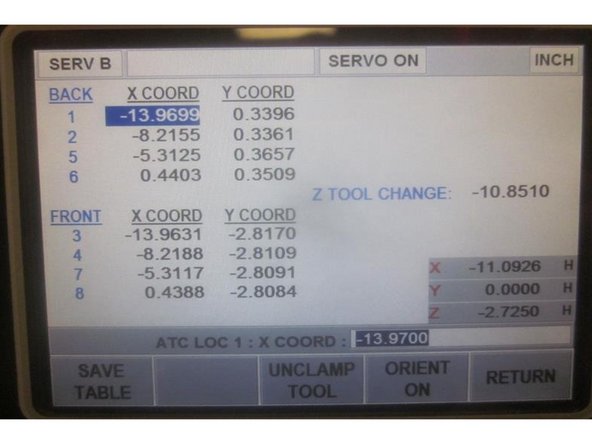
In DRO set the spindle speed at 150 rpms. Go to service code 520. Press the "ATC front " key then the "Input table" key. Install a tool holder in the number 1 position.
-
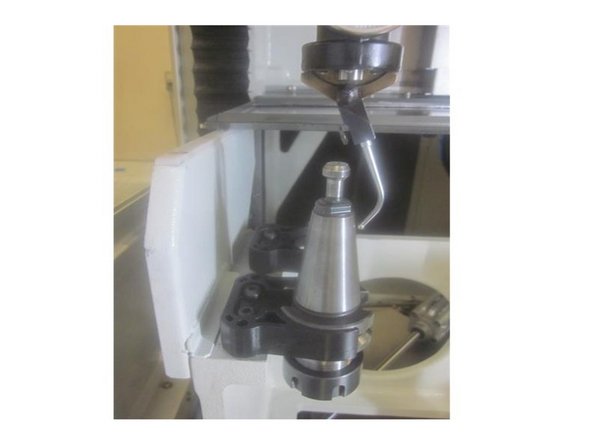
Using the co-axial indicator jog X and Y to the coordinated numbers for the number 1 position. Write down the X and Y numbers. Raise the Z axis, change to position 6 and repeat. Adjust the magazine so the "Y" numbers for position 1 and 6 are within .020" of each other.
-
If more adjustment is needed, underneath loosen the screws attaching the carriages to the linear guides. Snug one screw as a pivot and adjust the ATC. Use the front lower stops to aid positioning. When finished, go to Tool Loading and bring the ATC forward. Adjust the stops to obtain a .030" clearance.
-
Once the magazine is positioned correctly, snug down the screws gradually alternating from left to right. Once tight, check the Y positions again. Compare the numbers to the current ones shown in the table.
-
If the numbers are greater than .005," check all tool locations. After any changes press the "Save table" key.
-
Install the ATC lower sheet metal panel and door seal. Clean the threads on the screws and chase the threads in the ATC casting. Apply blue Loctite and snug up the screws not squishing out the seal.
-
Go to "Tool loading" and load and unload a tool in every position. Observe any excess movement in the tool grippers. Remove the test tool. Return the ATC under the rear column and mode out.
-
-
-
In DRO set the spindle speed for 150 RPM.
-
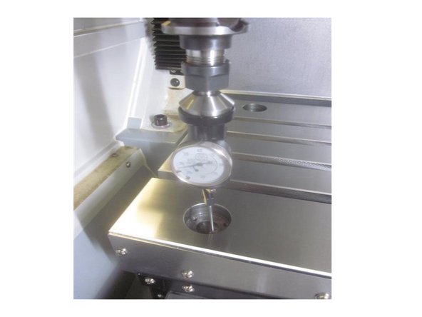
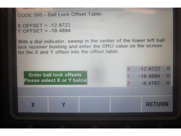
Go to service code 500. Using the co-axial indicator, sweep in the front LH ball lock location with the X and Y axis.
-
In the lower RH corner of the screen is a DRO. Select X and carefully jog the axis to coordinate with the ball lock. Enter the number from the DRO and press ABSet. Select Y and repeat.
-
-
-
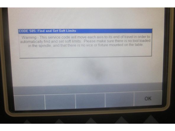
Caution: Remove all tooling from the table and the spindle before setting soft limits.
-
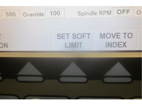
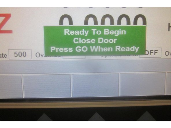
Go to service code 505. Press the "Set Soft Limits" key. A blue warning appears reminding of the caution above. Press "Ok" then "Go" and the machine rapids all axis to set the limits. When finished it will be in 505. Mode out.
-


