-
-
If performing a new machine installation, first remove the "red" shipping brackets attached to the X axis under the side sheet metal covers. Note: Brackets are found only on newer M11's.
-
Remove the left and right hand side sheet metal side covers and set aside. Remove the "red" brackets, set aside and save them in case the machine is moved or shipped.
-
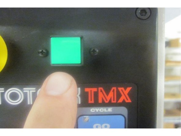
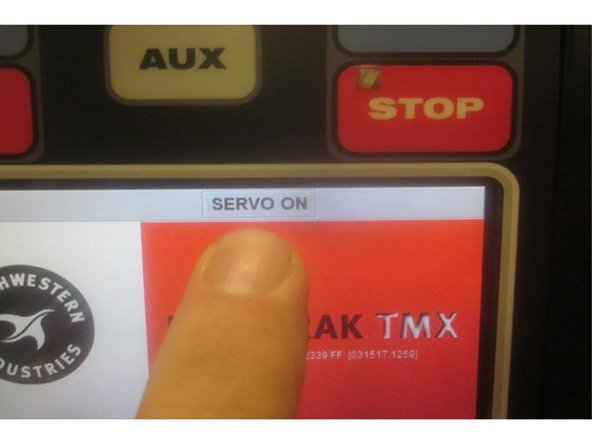
Power up the 2 OP and make sure the "Emergency Stop" switch is not activated. Energize the servos and listen for the servo amp to activate (thud). Home the machine. Mode out.
-
-
-
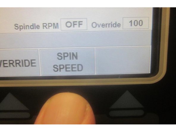
Press the DRO soft key. Press "Spindle Speed" soft key. Enter 150 from the key pad and press ABSet. Press "Mode." Press "RSRT" soft key.
-
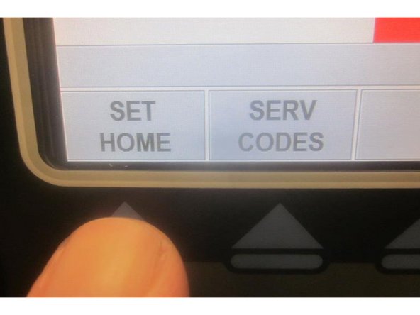
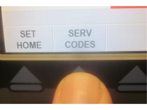
Press "Serv Code" soft key. (On M10 models press "Code #" key). From the key pad enter 520 and press ABSet.
-
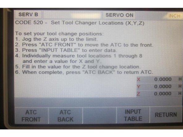
The display now reads "Set Tool Change Locations (X,Y, Z)." Press the "ATC Front " soft key. Press "Go" and the ATC comes forward.
-
Note: If you remove the door assist cylinder access panel you can depress the "door open" switch ( or use a zip tie to by-pass it ) which allows the door to remain open for service. Otherwise you will need to keep it closed during adjustments including tool changes.
-
-
-
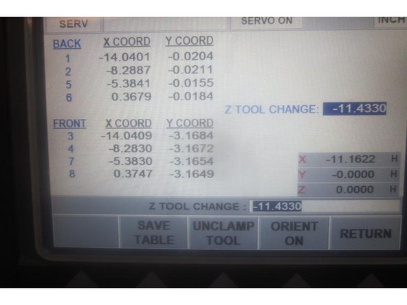
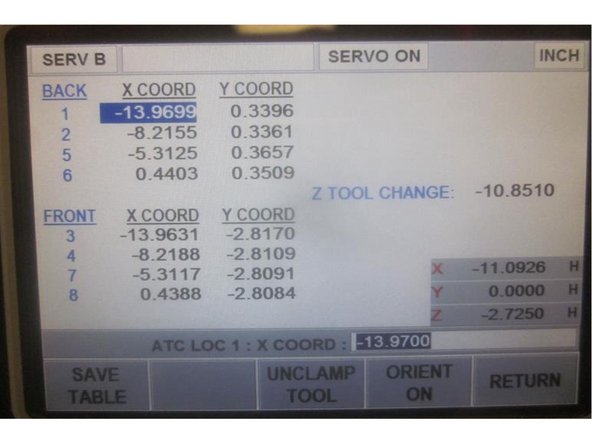
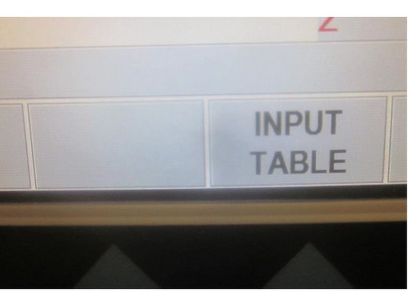
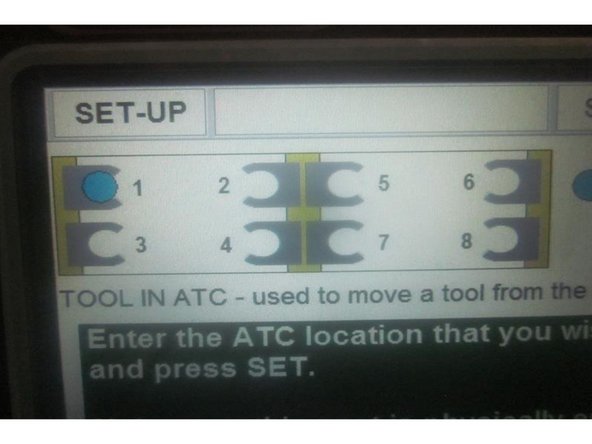
Press the "Input Table " soft key. The display now shows 8 Tool Locations and the Z Tool Change ( height). There is a DRO display in the lower RH corner that indicates current position of the spindle. Notice that Tool 1 in the X axis is highlighted. Rotating the hand wheel will move the highlight to different tool locations.
-
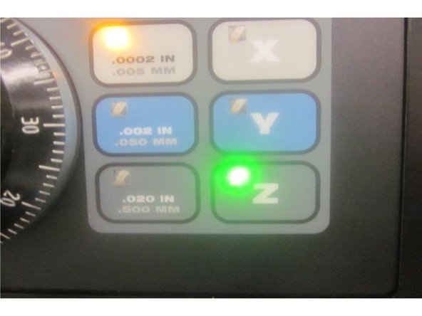
Use the hand wheel and the axis soft keys to jog the spindle in X,Y and Z. Note: you will not be able to highlight tool locations with any speed or resolution keys lit.
-
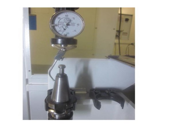
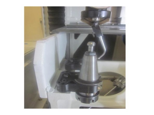
Install a Co-axial Indicator in a BT30 Tool Holder with a clamping journal.. Leave a slight amount of the pilot sticking out. Install the tool holder with the indicator into the spindle.
-
Manually install a second BT30 Tool Holder in the number 1 tool position in the ATC.
-
Use the hand wheel to jog the spindle approximately center over tool number 1. Turn the indicator so the lower arm guides (rocker) line up in the center of the tool holder in the X axis. Rotate the indicator 90 degrees and do the same for the Y axis. Adjust as necessary.
-
-
-
Using the Z axis lower the spindle guiding the indicator arm over the top of the tool holder allowing it to contact the tapered portion of the tool holder. Carefully adjust the spring tension on the arm so it has a slight load when contacting the tool holder.
-
Hold the indicator and turn on the spindle. As the spindle rotates the needle of the indicator moves back and forth. Using .001" resolution or smaller move both X and Y until the indicator needle stops.
-
Press ABSet to set X and the highlight moves to the Y axis. Press ABSet again. The highlight moves to tool number 2 in the X position. Raise the Z axis clearing the tool holder. Manually remove the lower tool holder and install it in tool position 2. Repeat the above outlined paragraphs here.
-
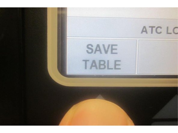
Press the "Save Table" soft key after every location is set. Continue through until finishing all 8 tool locations. Remember to press the "Save Table" key.
-
Once all 8 tool locations are set and "Save Table" has been pushed, jog the spindle to the # 4 tool location coordinates. Remove the tool holder with the coaxial indicator from the spindle.
-
-
-
Perform Service Code 510 (spindle orientation) before proceeding to set the Z axis tool height. Use your service manual to complete this step before continuing. You can also use the 2OP Final Inspection form for this step.
-
(If not already there) go to service code 520 and bring the ATC forward. Press the "Input Table" soft key. Jog the spindle with the hand wheel in X and Y to match the coordinating numbers for tool location 4.
-
Manually install a tool holder with a clamping journal in the #4 tool position in the ATC. Using the hand wheel highlight the Z Tool Change. Press the "Orient ON" soft key. The spindle will rotate and lock to align the drive dogs to load or unload a tool.
-
Press the "Unclamp Tool" soft key. Air will purge from the spindle center. Lower the Z axis over the tool holder. The air will start to diminish as you get near the bottom. Use the .0002" resolution and slowly lower the Z axis until the air "just stops." Raise it until the air "just starts" plus two clicks. Note this number.
-
Add (-) .010" to the number you noted. Enter the new number into the highlighted Z Tool Change ( height) and press ABSet. Press the "Save Table" soft key. Raise the Z axis enough to clear the tool holder. Remove the tool holder. Press the "ATC Back" soft key.
-
Example: Z axis in DRO reads -11.6500. Add .01." Now should be -11.6600. Remember to press the "Save Table" soft key after any changes.
-
Press the "return " soft key twice.
-
-
-
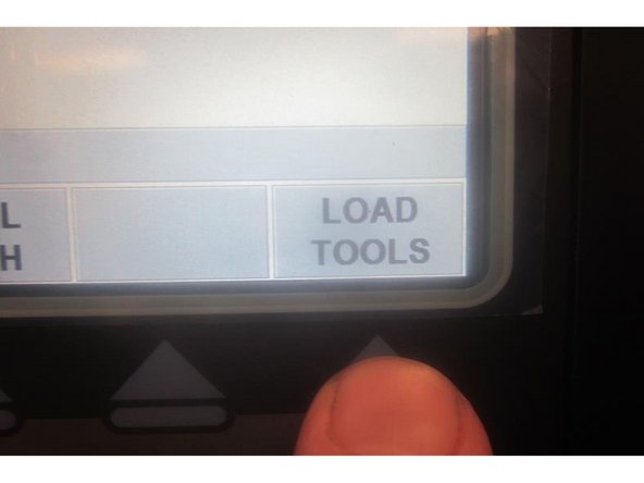
Go to "Tool Loading" and bring the ATC forward. Install a tool holder in the spindle. Note: The door switch needs to be activated to load tools.
-
To prevent a crash or damage to the machine, carefully observe the "prompts" during tool loading.
-
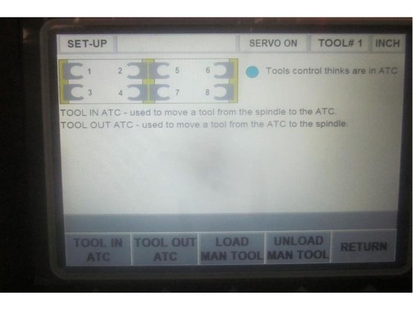
Press the "Tool in ATC" soft key. Enter the tool location and press "Go." The machine jogs to that location and prompts : Are you sure the tool change spot is empty? Press "Yes" then press "Go" and the machine loads the tool.
-
The display shows a tool loaded in the selected position and you can load another tool. Press the "Return" soft key" to return to the first screen. Press the "Tool Out of ATC" soft key. Enter the same position you loaded the tool to and press the "Go" soft key. The machine prompts: Are you sure the spindle is empty?"
-
Press "Yes" then "Go" and the machine unloads the tool. Check tool loading and unloading in all 8 positions. Observe the plastic tool grippers for excessive movement. It may be necessary to adjust the Z Tool Change (height) or minor adjustments in X and Y to obtain smooth load / unload action.
-
After you have finished checking all the tool locations press the "Return" soft key twice and then the "Go" soft key. Press the "Mode" soft key.
-
For new factory builds load the tool loading program 55555555 .PT4 and run the program.
-

Cancel: I did not complete this guide.
One other person completed this guide.