Tools
- Metric hex keys
- Metric hex sockets
- 4mm "stubby" hex key
- 3/8 drive ratchet
- 3/8 drive extension 6 inch long
- 9/16 or 14mm deep 3/8 drive socket
- 12mm, 14mm, 17mm open end wrenches
- tefflon tape
- 2 cups ISO 32 oil
- small disposable styrofoam coffee cup
- Complete BT30 Tool Holder
- M10 or M11 Service Manual
- 4 each 4x4 wood blocks 12 inches long
Parts
No parts specified.
-
-
Start up and HOME the machine. Remove any tooling or fixtures. Remove the bottom sheet metal cover surrounding the spindle and set aside.
-
In DRO center the spindle over the table. Lower the Z axis until the spindle is 12 inches from the table.
-
Remove the front cover panel and carefully separate the white clamp / unclamp button from the panel.
-
-
-
Disconnect the "Clamp / Unclamp" switch mounting plate from the casting and set in between the motor casting and the sheet metal.
-
Remove the "Clamp / Unclamp actuator plate. Use a "stubby" 4mm hex key.
-
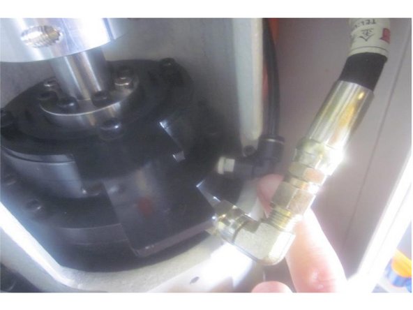
Place a small cup in the front lower RH corner of the spindle housing. Remove the hydraulic line at the elbow and let the oil drain into the cup then remove the oil fitting. Note: it will be necessary to empty the cup to catch all the oil.
-
Disconnect the air line from the "push to connect" 90 degree fitting and remove the fitting.
-
On M11's remove the air line to the spindle located in the three o'clock position on the spindle lower main flange. Remove the 90 degree elbow fitting if replacing the spindle.
-
-
-
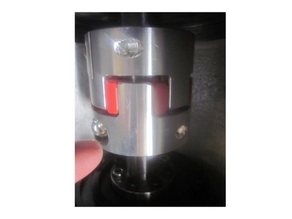
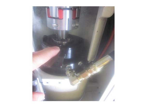
Break loose the lower spindle coupler screws.
-
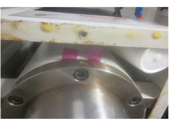
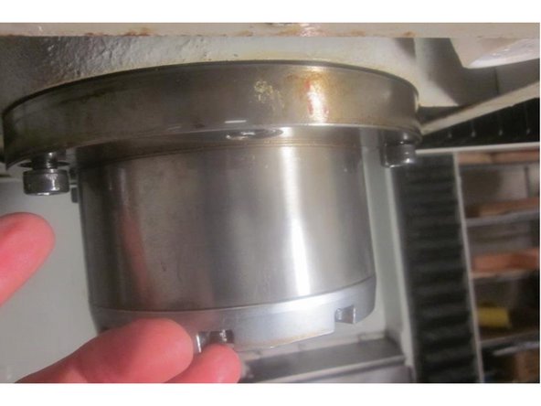
Raise the Z axis and loosen the six (6) 8mm screws that retain the spindle in the motor housing. Look for shims noting their orientation. Remove the shims and set aside. Remove the four (4) 8mm screws on both the left and right side of the spindle. Leave the front and rear screws ( 6 and 12 o'clock) in place.
-
-
-
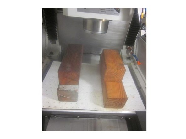
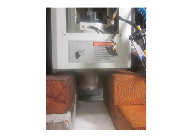
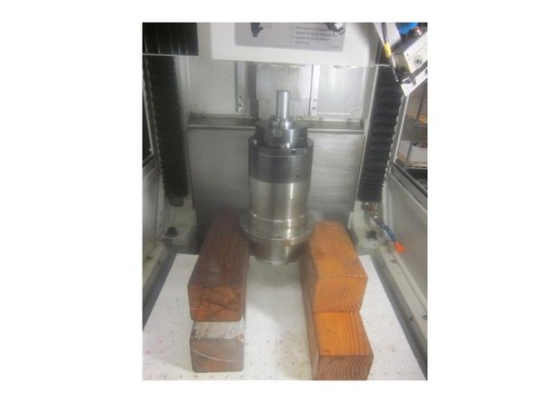
Place the four (4) wood 4 x 4 blocks on the table on either side of the spindle. This setup allows you to easily get to the remaining bolts. Try to use blocks that are even heights as this eases removal and installation.
-
Lower the Z axis until the spindle contacts the blocks. Loosen the front and rear bolts a bit then raise the Z axis to leave just a slight gap in between it and the spindle.
-
Remove the front and rear spindle bolts. The spindle will rest on the wood blocks. Slowly raise the spindle until it clears the housing. Remove the spindle.
-
-
-
Place the spindle on the wood blocks. Use the X, Y and Z axis' to guide it back up into the housing. Check that the stub shaft inserts into the coupler. Lower the housing leaving a slight gap. Start the front and rear screws leaving a couple of threads.
-
Raise the Z axis and install the remaining screws. Replace the shims and tighten all the screws firmly and evenly in a star pattern to 24 ft. lbs. Before tightening the lower coupler screws, adjust the gap in the coupler to approximately .100." Tighten the lower coupler screws .
-
Install a zip tie around the upper clamp / unclamp switch to activate it. In DRO set the spindle speed at 500 RPM. Turn on the spindle and listen for noise. Gradually raise the RPM observing and listening for noise or vibration. Use care around moving parts.
-
If the spindle is noisy try loosening all the coupler screws and check the coupler alignment moving the coupler up and down on the shaft (s).If the spindle is still noisy or vibrates it may be necessary to break loose the spindle motor mounting screws, the coupler screws (or both) and retighten them to improve alignment.
-
To gain access to the spindle motor mounting bolts remove the top, left and right sheet metal spindle enclosure panels. Break loose the screws, let the spindle "relax" and re-tighten the screws. If you perform this step run through the RPM range and check again.
-
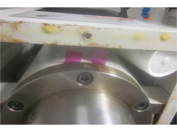
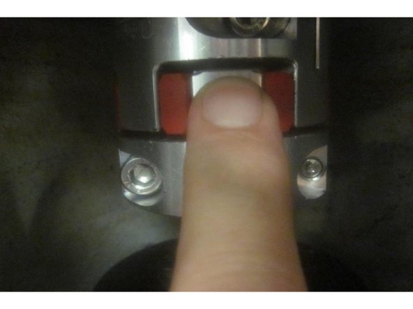
Remember to leave a gap of approximately .100" between the plastic and aluminum pieces of the coupler.
-
-
-
Clean any debris from the holes in the spindle where the air and hydraulic fittings attach. Clean the air and hydraulic fittings. Install Teflon tape on the portion threaded into the spindle. Install the air fitting first then connect the air line. Next do the same for the hydraulic oil line.
-
On M11's install the 90 degree spindle air line fitting in the main lower flange at the 3 o'clock position if replacing the spindle. Install the air line. Do not over tighten the line. Check that air flows through the end of the spindle.
-
Re-install the 'Clamp / Unclamp" switch actuator plate. Note: On older M10s the spindle has a "anti rotation" plate. If you are working on one of these units or the replacement spindle has one it may be necessary to adjust the switches to make the clamp / unclamp mechanism function.
-
If the control panel displays a "Clamp / Unclamp error or fault, the switch may need to be raised or lowered to prevent this. Usually it's the upper switch.
-
-
-
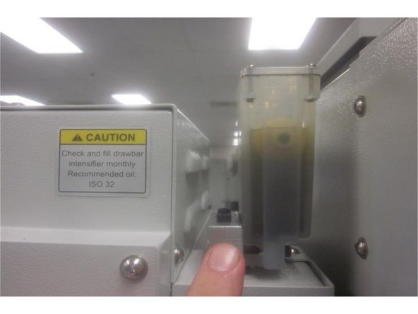
If the spindle performs well and there are no vibration or noise issues, fill the "Clamp / Unclamp" reservoir 3/4's full with ISO 32 oil. Use the oil removed if it's not contaminated.
-
Continually press (cycle) the tool clamp switch observing the oil level. The system bleeds as you"cycle" the switch. Observe the front switches and listen for air from the spindle. Monitor the oil level. Do not let the reservoir run empty. When no more bubbles purge be sure to fill the reservoir to 3/4 full.
-
When the system is bled, the switch plate will depress both switches completely.
-
Reassemble and install the front panel connecting the white tool clamp button. Install the bottom sheet metal panel.
-
Perform Service Code 510 Spindle Orientation. Use your service manual to complete this task.
-
Test fit a tool in the spindle. Remove it and note the "bump out." It should be approximately .020." After the spindle orientation is complete, check that the spindle will load and unload all tool locations without issues. Observe the Z tool height as well.
-
If the machine has tool loading issues refer to your service manual to adjust the tool positions or the Z tool height. This is normally not an issue with a spindle change, but ensures the spindle orientation is correct and functional.
-
Cancel: I did not complete this guide.
One other person completed this guide.


