Tools
- 9 inch x 12 inch granite stone
- .0005 tenths coaxial indicator
- BT30 Tool holder with .375" collet
- 1 BT30 tool holder with clamping journal
- Metric hex keys
- Metric hex sockets
- 3 8 drive ratchet extensions and adapters
- Small slide hammer (dent puller)
- 0-100 ft./lbs. torque wrench
- 8mm 3 8 drive deep hex socket
- 6mm 3 8 drive deep hex socket
- 6 inch adjustable wrench
- Utility knife
- silicone sealer
- protective work gloves
- .0001 tenths indicator with magnetic base
- 5/32 inch hex key
- small piece of brass or aluminum stock .5 x .5 x 3 inched long
- 1.250 inch "Crow's Foot" wrench
- special lifting tool and kit
- Tapered Punch
- Small pick or screwdriver
Parts
No parts specified.
-
-
Power up and home the machine if possible. If you cannot, use service code 505 to move the axis. You will need power to complete this guide.
-
Remove any tooling fixtures from the table and any tools from the spindle. Clean the top of the table. If the table is rough, it may give false readings. Check the level of the machine. If the machine is to be moved for this procedure, level the machine again. Make sure equal pressure is on all leveling feet.
-
Note: The rear of the machine is heavier so the pressure will feel greater on the rear feet.
-
Check the table flatness. Set up the indicator from the center of the spindle to touch the inner front corner of the front LH ball lock as 0. Check the other ball lock inner corners and note the flatness.
-
Remove the LH and RH upper side sheet metal access panels. Remove the rear cover for the Y-Axis/ATC.
-
Raise the Z-Axis and disconnect the air. Disconnect the ATC door at the air cylinder. Remove the four screws holding the ATC door to the column and remove the door. Remove the ATC door assist brackets located on top of the ATC main casting.
-
Use caution if working with the power on. Use the E-stop button for safety.
-
-
-
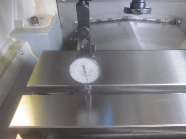
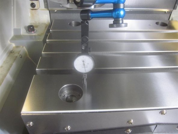
If possible, measure the perpendicularity for a reference. Make sure the work table surface is clean and smooth. Irregular table surfaces will affect the measurement.
-
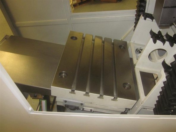
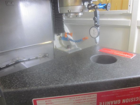
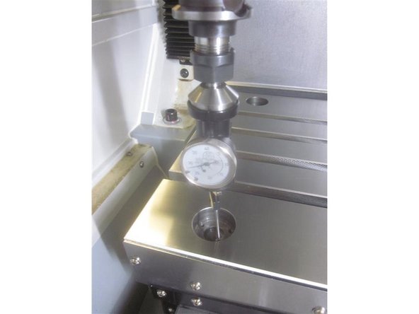
Place the (tenths) indicator close to the center of the spindle (as shown). Place the granite stone on the table with the long edge towards the rear. Line up the long edge with the front edge of the ball locks. Line up the RH side with the inside edge of the RH ball locks.
-
Starting in the rear RH side, jog the Y-Axis fore and aft while adjusting the stone until the indicator reads 0 throughout the travel length. Without touching the stone, adjust the indicator to check the X-Axis. Start at the RH side working towards the left. If the perpendicularity is over .001", it will need correction. Note the measurement.
-
-
-
Remove the RH and LH front lower side panels that cover the chip tray and coolant tank. Remove the Y-Axis ball screw protective cover (small panel). Remove the chip tray. Drain the coolant tank. Remove the coolant tank. As the tank clears the front of the machine, remove the coolant pump and set inside the machine.
-
Remove the main ATC air cylinder from its rear mount via the pivot pin, and re-install the pin and "e" clip. Disconnect the air cylinder at the rod end, leaving the rod end attached to the ATC carriage. Note the "depth" which the shaft is installed at for ease of re-assembly and adjustment.
-
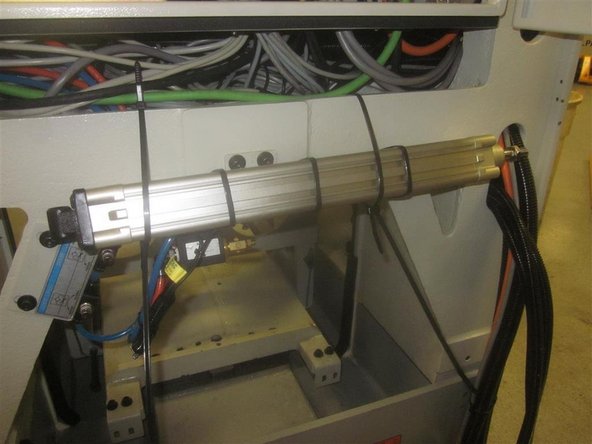
Using zip ties, roll up the cylinder, and tie it to the machine casting out of the way through the bottom of the electrical panel. Tie up the door cylinder to the casting as well.
-
-
-
Remove the sheet metal wiper covers (both front and rear) from the table.
-
Remove the ATC wiper cover and seal.
-
-
-
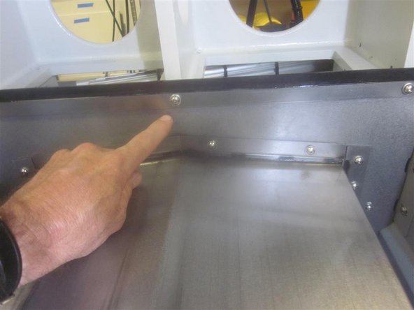
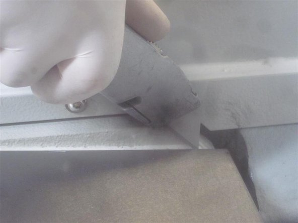
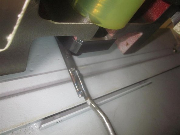
Using a utility knife, carefully cut through the white sealer located at the front of the bridge between the Y-Axis cover and the main base casting.
-
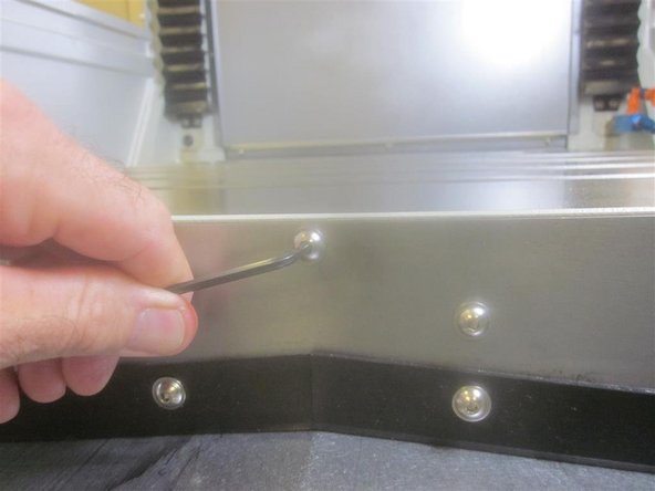
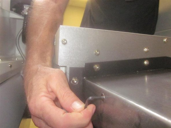
Remove the six (6) FHSC screws from the sides of the Y-Axis cover.
-
Remove the narrow sheet metal cover strip located inside front of the machine above the Y-Axis cover. This gains full access to the front of the bridge.
-
-
-
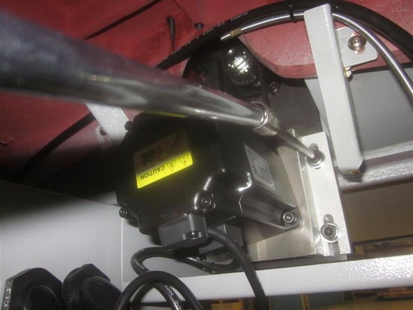
Remove the sheet metal drip pan underneath the Y-Axis motor. Remove the Y-Axis motor and belt, and set the motor aside. Do not disconnect it. Remove the motor mounting plate.
-
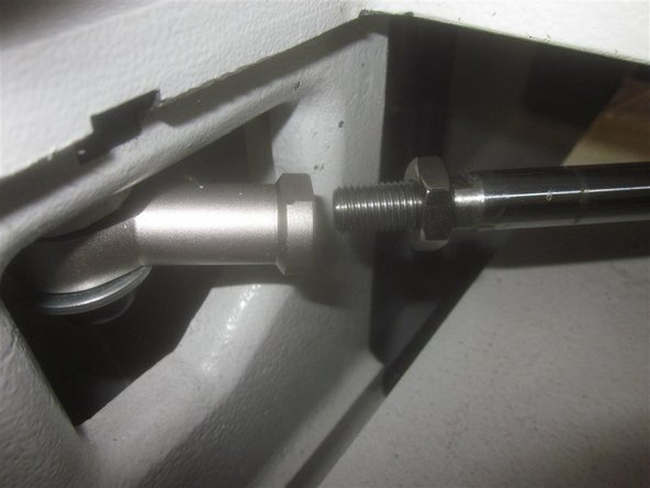
Using a 19 mm wrench and 6mm hex key, place the key against the machine. Remove the nut, star washer, flat washer, sprocket, brass ferrule, and the woodruff key.
-
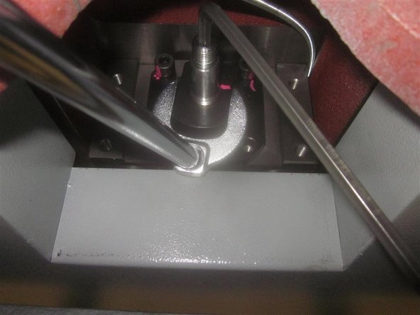
Loosen the clamp nut lock screw with a 5/32 hex key. Place a 6mm hex key in the end of the ball screw against the machine. Remove the clamp nut with a 1 1/4 inch crows foot wrench.
-
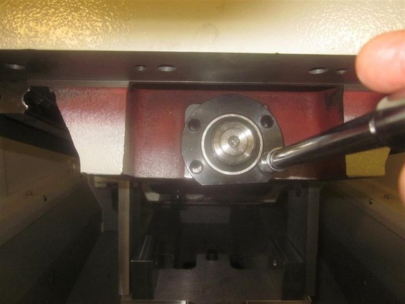
Remove the four (4) 8mm SHCS that hold the rear bearing housing in place and remove the housing.
-
-
-
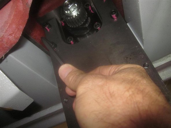
Slide the Y-Axis cover fore and aft to gain access to the bridge mounting screws.
-
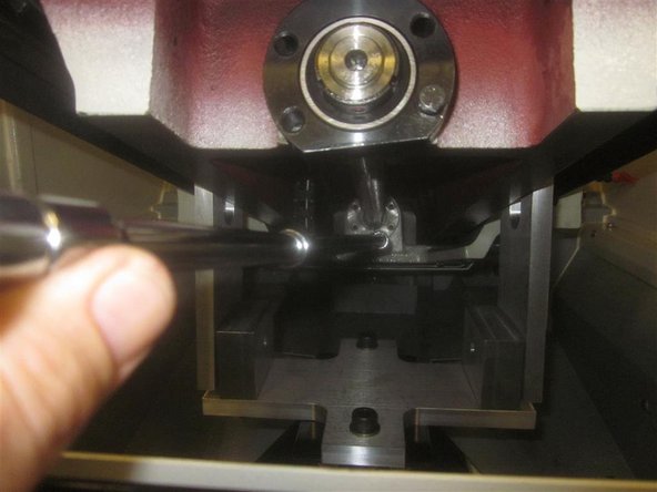
Using a slide hammer (dent puller) or similar tool, remove the two (2) tapered pins (one on each end) from the bridge. Remove the (7) seven 8mm SHCS that attach the bridge to the base casting.
-
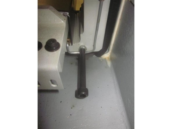
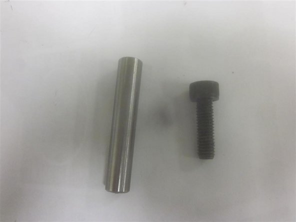
Remove the two (2) 10mm x 120mm SHCS installed in the rear of the ATC carriages. Note their "depth" for ease of re-assembly and adjustment.
-
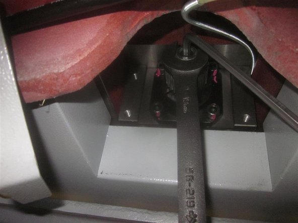
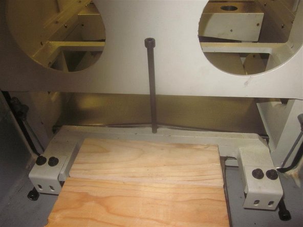
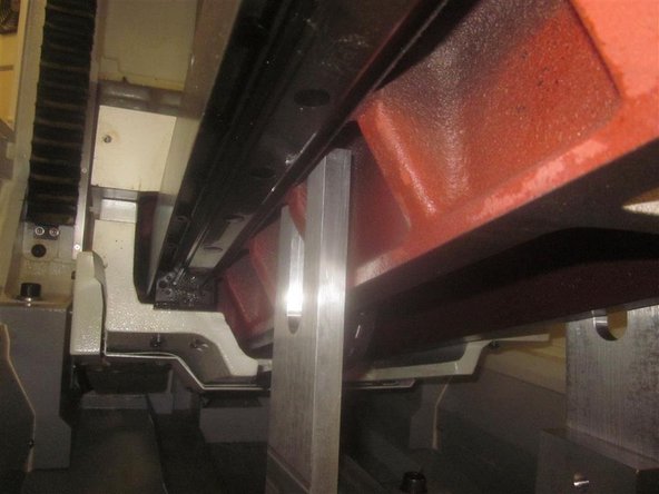
Place the plastic block between the rear of the bridge and the main base casting to prevent the bridge from rear movement. Raise the Z-Axis as high as possible. Install the 8mm x 160mm SHCS in the threaded hole in the rear of the bridge casting. This will hold the ATC and table in place while working on the machine.
-
-
-
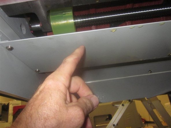
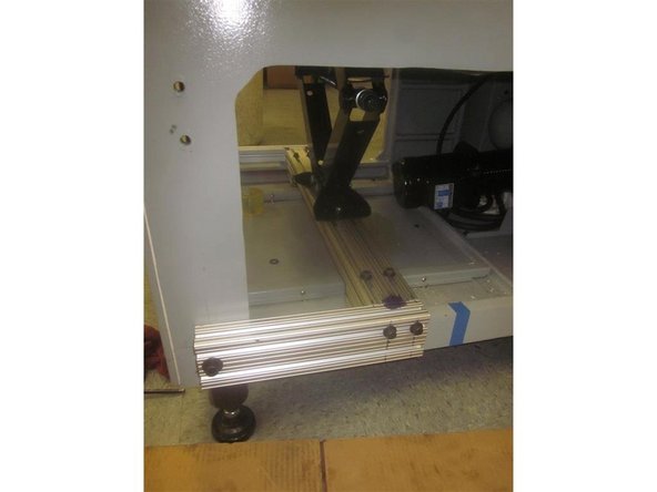
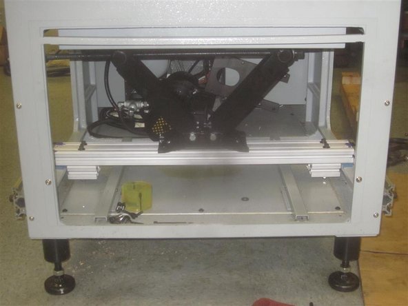
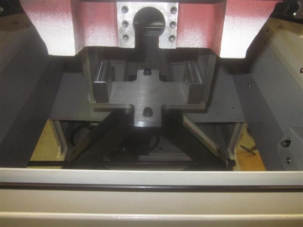
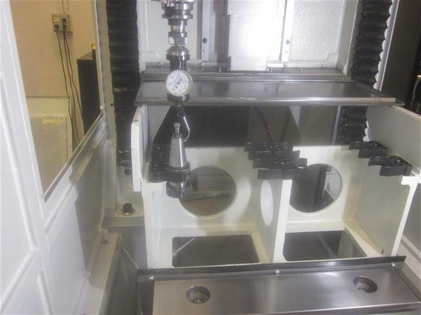
Place the 1 1/2 x 3 x 30 1/4 aluminum frame piece and rest it on the machine casting with the short square pieces facing down (shown on the image). Attach the side supports. Install the jack to the main frame. Attach the main "U" support to the top of the jack. Leave all fasteners slightly loose for minor adjustments.
-
Slowly raise the jack guiding the upper floating "U" shaped plates while capturing the ribs on the bottom of the bridge, just barely contacting the casting (pic). Now tighten up all fasteners, except the shoulder bolts that are attaching the "U" plates to the horizontal plate. These are loose in order to allow for casting variation.
-
Note: The "U" supports are designed to rotate slightly as the bridge is lifted. When first set up, they should lean towards the front of the machine.
-
-
-
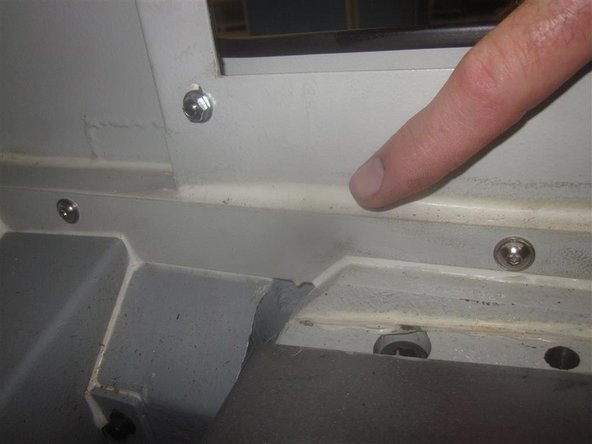
Remove the plastic block (temporarily), and look for shims placed between the rear of the bridge and the ground spacer.
-
Using a 4mm hex socket, locate and tighten the two (2) set screws that are raising the bridge, and look for shims. Look carefully as they can be stuck to the top or bottom side, out of view. Use a pick or similar, and remove the shims. Back off the set screws when completed. Replace the plastic block when completed.
-
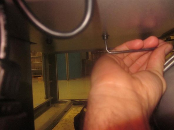
A mirror is helpful for looking for shims.
-
Replace the shims reversing the previous step before tightening the main screws on the rear of the bridge. Perform this later during re-assembly.
-
Jog the table rearward until it contacts the ATC carriages.
-
Using a 3/4" or 19 mm socket, slowly raise the jack lifting the bridge. Raise the bridge until you have complete access to the ball screw.
-
Note: As the bridge rises, it will contact the "angled" front face of the plastic block placed in the rear earlier.
-
-
-
We recommend changing all bearings when changing a ball screw.
-
Thoroughly clean the bearing housing and related parts before beginning the assembly process.
-
Make sure that the new bearings are properly greased. Carefully wipe off any excessive grease from outside surfaces of the bearings. This ensures accuracy.
-
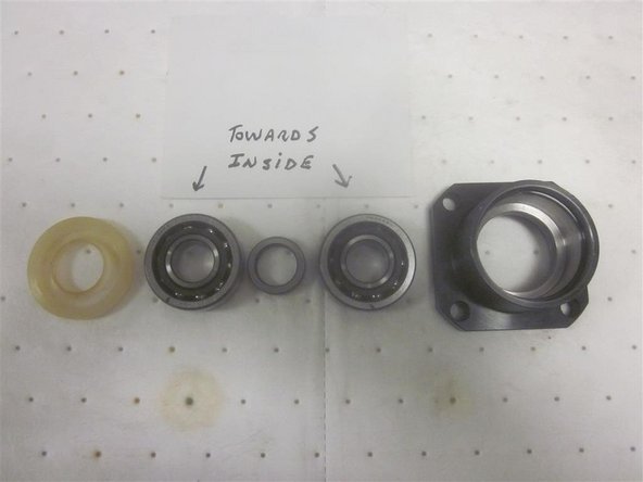
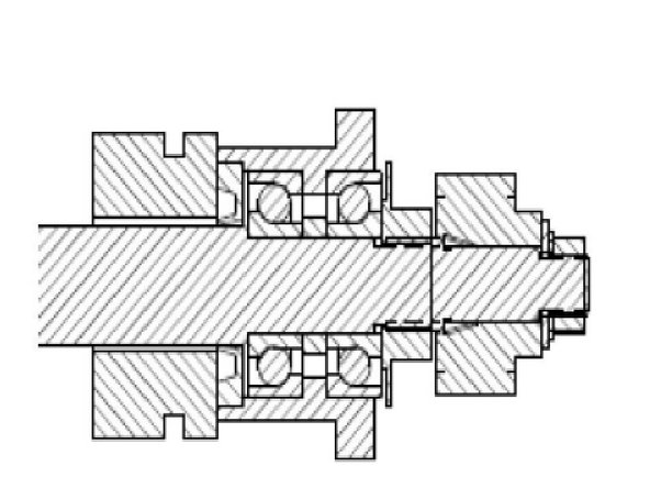
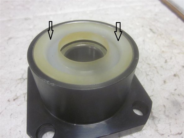
Install the angular contact bearings into the housing with the spacer in between. The bearings should be "back to back" as shown. Tip: The narrower inside races face each other. Install the seal open side out,
-
-
-
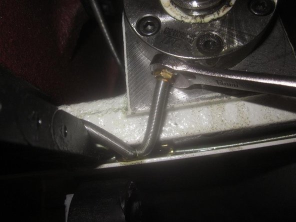
Remove the oil line attached to the ball nut. You can perform this before raising the bridge.
-
Remove the five (5) 5mm SHCS that are attaching the ball nut to the yoke casting. You can perform this before raising the bridge. Push the work table rearward until it contacts the ATC; make sure that both pieces contact the long 8mm SHCS.
-
Remove the four (4) 6mm SHCS that are attaching the front bearing housing to the bridge. Note: Some early machines use SHCS, while later models used hex head screws.
-
Remove the ball screw.
-
With the ball screw on a work table, remove the ring nut that is attaching the front bearing to the ball screw. Loosen the set screws, and tap them with a piece of brass or aluminum. This eases removal. Remove the bearing and housing from the ball screw.
-
-
-
Thoroughly clean all related parts and machined surfaces before performing the installation, especially the mating surfaces of the bridge to the base casting.
-
Install the roller bearing into its housing. Carefully install it on the end of the ball screw. It is a precise fit, and may require a light "tap" to seat it. Install and tighten the ring nut (lube the set screws). Tighten the set screws.
-
Rotate the ball screw, so the ball nut is in the same position. Insert the ball screw through the yoke casting. Install the ball nut screws, and lightly secure. Install the oil line. Install the front bearing housing screws, and lightly secure.
-
-
-
On M11's, make sure the rear ground spacer is lined up on the main base casting before placing the bridge. The brass tapered punch (provided) can help align the holes. Lube fasteners before starting work.
-
Carefully lower the jack placing the bridge back on the main base mating surface. It may be necessary to align the spacer plate with the holes. Install the seven (7) 10mm SHCS front and rear. Install them only a few threads.
-
Once the bridge is placed and the screws are installed, remove the long 8mm SHCS and the plastic block from the rear of the bridge.
-
If there were shims in the rear, now is the time to re-install them. As before, raise the bridge with the set screws, install the shims, and then back off the screws. Now snug up only the center rear screw.
-
Install the rear tapered pin. Note: The rear tapered pin may need to be removed to adjust perpendicularity, but leave it in for now as a base reference.
-
-
-
Lube all fasteners. Install the rear bearing housing. It may be necessary to wiggle it a bit to align the spacer. Install two screws in the upper holes, and snug them up. Install the clamp nut (lubed) and torque to 50 ft.-lbs. Torque the clamp nut lock screw (lubed) to 60 in.-lbs. Install the lower bearing housing screws, and snug them up.
-
Note: Access to the various fasteners is limited, so use your judgement when tightening them. Although you can tighten the components with the bridge raised, if the rolling torque is out of spec when the bridge is in place, it will be necessary to adjust it with the bridge in place.
-
Lube all fasteners. Rotate the ball screw to move the yoke casting rearward, close to the steel block where the rear bearing housing attaches. Torque the rear bearing housing screws in a crisscross pattern to 14 ft.-lbs.
-
Tighten and torque the ball nut screws in a star pattern to 7 ft.-lbs. Install the front bearing cushion, and tighten securely.
-
Rotate the ball screw so the ball nut is close to the front bearing cushion. Torque the mounting screws for the front bearing in a crisscross pattern to 11 ft.-lbs. Note: Gaining access here is difficult. Use your discretion when tightening the screws. Use the "special" wrenches provided.
-
-
-
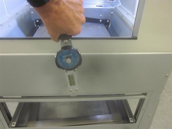
Check the rolling torque front, center and rear. Without the motor belt installed, it should be 5-7 inch-lbs. in all three positions, and not vary more than 3 in-lbs. Max torque is 10 in-lbs.
-
Install the woodruff key, brass ferrule, sprocket, flat washer, star washer and nut. Tighten securely.
-
Install the motor plate. Note the position of the oil line (located in the upper right corner). Be careful not to pinch the line, or the plate may not align itself. Tighten securely.
-
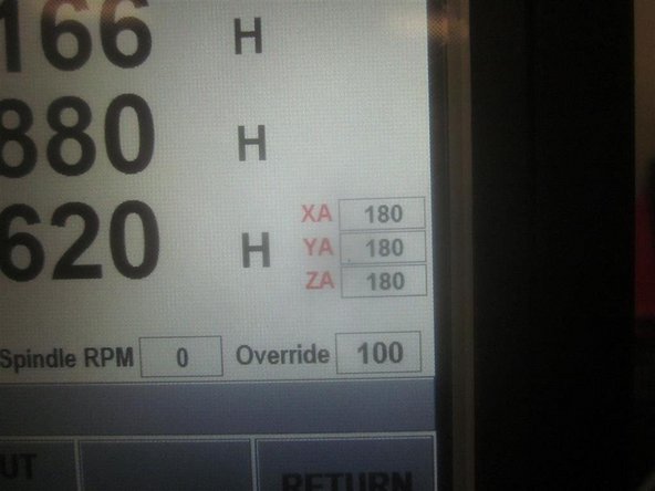
Manually move the table forward until the ball nut touches the front cushion. Let it "relax" and back off the cushion one full turn. Power up the machine, go to service code 505, and set the Y-Axis to 180. Leave the servos activated. Install the motor and tension the belt.
-
-
-
Check the rolling torque again on the front, center, and rear areas. Use the E-stop to turn off the servos before checking. It should be 10 in-lbs. or less, and within 3 in-lbs. in all three places. Average rolling torque is 6-7 in-lbs. with the motor belt installed.
-
In service code 505, slowly jog the table rearward 1 inch towards the front, and check the Y-Axis index angle. If out of spec, adjust accordingly. Normal range is 135-225. If in spec, use service code 203 to "home" the machine.
-
If the rolling torque is out of spec, try breaking loose the ball nut and re-torque it in the "high" location. Re-check again in all three locations.
-
If the rolling torque is still high, it may be necessary to jog the axis to either end, break loose the ball nut, bearing housing (or both) screws, and re-torque them. Check the rolling torque after any adjustments.
-
-
-
Clean the work table surface. If the surface is poor, it may be necessary to clean up the surface with scotch brite, or crocus cloth and a flat bar. Surface irregularities can affect your measurement. Check the machine level, and adjust if necessary.
-
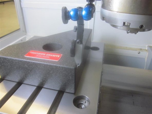
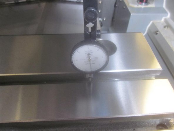
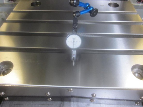
Place the granite stone on the table. Line up the long edge in X on the inside edge of the rear ball locks. Line up the Y side along the RH inside edge of the ball locks.
-
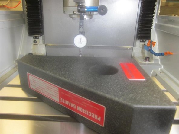
Set the tenths indicator as close to the center of the spindle as possible. Place the stylus of the indicator along the RH side of the stone at the rear corner. Jog Y back and forth while adjusting the stone, until it reads 0 along the full length of the stone.
-
Without moving the stone, adjust the indicator to measure off the rear edge. Jog X left and right, and check the indicator. If the reading exceeds .001", move the bridge by shifting the front until the indicator measures less than .001" (preferably less than .0005" ).
-
If there isn't enough adjustment, pull the tapered pin from the rear, and loosen the center bolt. Shift the rear of the bridge to a favorable position, and check X again. This may require several tries (both front and rear) to bring the bridge in spec (.001" or less, but preferably less than .0005").
-
Tighten up the rear center bolt.
-
When the squareness is in spec, carefully tighten the bridge screws evenly in three steps while checking the indicator for movement. If the bridge moves out of spec, loosen the screws, and start over.
-
Once the X measurement is in spec, adjust the indicator, and re-check the Y-Axis. It must read zero on the back and front of the length of the stone. Then double check X again.
-
-
-
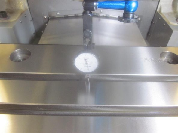
Clean the "walls" of the "T" slot prior to measuring. Be sure no chips, debris or residue is present, as this could affect the measurement.
-
Set up the indicator to touch off the front wall of the "T" slot. Use the ball locks as a reference.
-
In DRO, jog the X axis left and right. The spec is .001" over 10 inches." If out of spec, loosen the table mounting screws. Snug up one corner screw. Adjust the table so that the indicator reads less than .001" (preferably .0005" or less). Tighten up the table screws securely.
-
Position the Y-Axis ball screw cover, and install the six (6) FHSC screws.
-
-
-
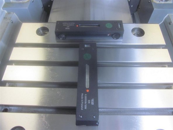
Check the machine level. Adjust it to match your original measurements (if necessary).
-
Check the table flatness. Starting at the LH front ball lock inside corner as "0," check the other ball lock locations. Adjust the legs to achieve a flatness of less than .001", or match your original measurement.
-
Note: If everything was cleaned properly, most likely the table flatness will remain mostly unchanged.
-
Check the tram. Adjust the legs to achieve a tram measurement of less than .001", or match your original measurement.
-
-
-
On M11's, the "soft limits" are set when the machine "homes."
-
On M10's, see below.
-
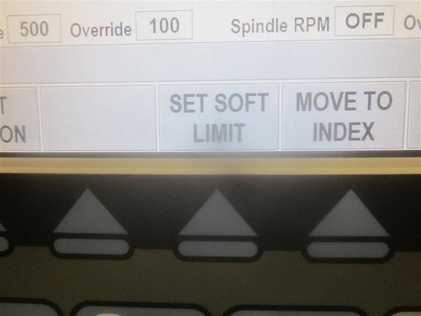
Power up, and "home" the machine. Go to service code 505. Press the "set soft limits" key.
-
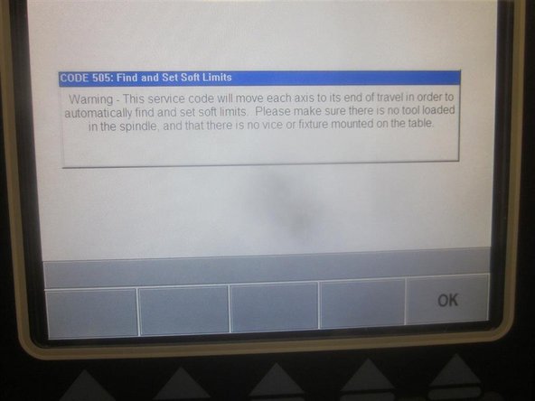
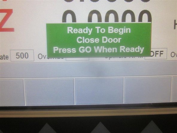
A "blue" warning appears on the screen. Make sure the spindle is empty, and nothing is on the work table.
-
Press the "go" key. The machine will rapid, and set the soft limits. After it finishes, press the mode key.
-
-
-
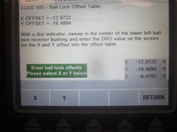
Install a tool holder with the co-axial indicator in the spindle. Go to DRO, and set the spindle speed at 150 rpm. On M11's, go to service code 500. (On M10's, press "code number" first, then enter 500, and press ABS SET).
-
Use the hand wheel to sweep in the indicator to the center of the front LH ball lock. Once in position, select X axis, and enter the number from the DRO in the lower RH corner. Select Y-Axis, and enter the coordinating number in the DRO. Press ABS SET.
-
-
-
Re-assemble the ATC air cylinder. Install the ATC door, including the door assist brackets. Connect the air. Check the distance the ATC travels by noting its position during "Tool Loading", and service code 520. Also, check that it fully closes when retracted. Adjust as necessary.
-
Check all the tool locations. If in spec (within .002"), do nothing. If you need to adjust, loosen the eight (8) SHCS underneath that connect the ATC carriages to the linear guides.
-
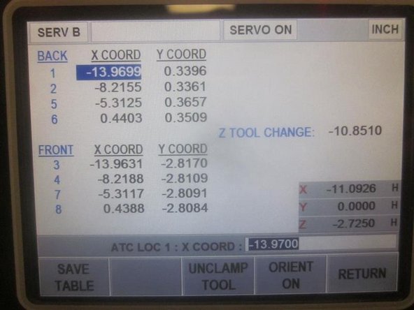
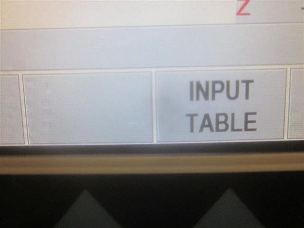
Go to DRO. Set the spindle speed at 150 rpms. Go to service code 520. Press the "ATC forward" key, then "Go" key. Press the "input table" key. Write down all the tool location numbers for X and Y, including the Z tool height.
-
Adjust the ATC lower stops, so they "just touch" the work table. Do not tighten the jam nuts.
-
With the ATC forward with air pressure, place a tool holder with the co-axial indicator in the spindle. Place another tool holder in the #1 tool position. Using the hand wheel, sweep in the tool location for #1, and enter the X and Y coordinating numbers. Press the "Save Table " key.
-
Repeat the step for tool #6, then the other positions. Compare the Y-Axis numbers. The ATC needs to be + or - .010." Use the stops to adjust fore and aft to bring the ATC into spec. Snug up the screws, and check again. If within spec, tighten up the screws a little at a time while working back and forth. Re-check after tightening.
-
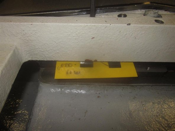
Remember to press the "save table" key. Once all locations are entered and the ATC screws are tight, go into "tool loading", and adjust the lower stops to obtain a .030" clearance, and tighten the jam nuts.
-
In "tool loading," load and unload a tool in each location while observing for smooth operation. Adjust any locations if necessary. Remember to press the "save table" key if you make any changes. If deflection (up or down) occurs, check the Z tool height, and adjust if necessary.
-
-
-
Install the ATC door seal and three (3) screws. Thoroughly clean the screws, use a 5mm tap to clean the thread, and blow out with air. Place a drop of Loctite 242 (blue) on each screw. Install the screws, and tighten (just "snug"), so the seal is not pushed out of position.
-
Before installing the work table wipers, break loose the wiper screws. After mounting the wipers, use a piece of paper to set the clearance between the wipers and the cover.
-
Install the drip pan under the Y motor. Install the sheet metal panels. Install the Y-Axis ball screw protective cover.
-
Clean the area surrounding the front of the bridge. Clean and install the narrow sheet metal strip in the front of the bridge just above the Y-Axis cover. Apply silicone sealer to the front casting area, and install the strip.
-
Install and adjust the 10mm SHCS on the rear of the ATC carriages. Set a clearance of .060", with the ATC all the way back with air pressure. Check the clearance by activating the ATC in tool loading. When it returns back, the bolts should not contact the rear casting. Adjust accordingly.
-
-
-
As a final step, re-calibrate the Y-Axis. Note: New versions of 2 OP software have slight changes that can affect service.
-
You must "clear" the backlash and "calibration" figures from the computer to correctly re-calibrate. DO NOT try to calibrate over known info that is stored in the computer. If you do, it will affect the accuracy.
-
Start up and home the machine. Go to service code 128, and write down the backlash for the Y-Axis. Clear the Y-Axis, and go to service code 123. Write down the calibration number and clear it. Note: The display MAY NOT CLEAR.
-
If the calibration number still appears, shut down the machine, wait 20 seconds, and start up again. Go to service code 123, and repeat "clearing" the calibration. The number should "zero" out. Shut down again and start over.
-
Follow the maintenance manual procedure for completing the Y-Axis calibration.
-