Tools
- Metric hex sockets
- Metric hex keys
- 19 mm (or 3/4) open end wrench
- 1 1/4 inch or 32 mm Crow's foot wrench
- co-axial indicator
- 3/8 drive ratchet
- 0-100 ft./lbs. torque wrench
- 30-250 inch pound torque wrench
- 0-75 inch lbs. torque meter
- 8mm open end wrench
- BT30 Tool holder with .375" collet
- 1/2 inch dia. x 3 inch long brass or aluminum stock
- 5/32 / 4mm extended or deep hex socket
- 1/4 to 3/8 socket adapter
- 3/8 to 1/4 socket adapter
Parts
No parts specified.
-
-
If the X-Axis can be moved under power, check and note the X index angle prior to disassembly. Go to service code 505, and jog the axis towards the RH side. When near the switch, use the .0002" resolution until the limit switch just lights. Note the index angle.
-
Remove the LH and RH side sheet metal side covers. Remove the LH and RH X axis bellows / accordion ball screw covers. Removing the LH spindle sheet metal cover adjacent to the bellow covers to ease removal and installation of the ball screw.
-
-
-
Loosen the three (3) screws on the X-Axis motor plate and remove the belt.
-
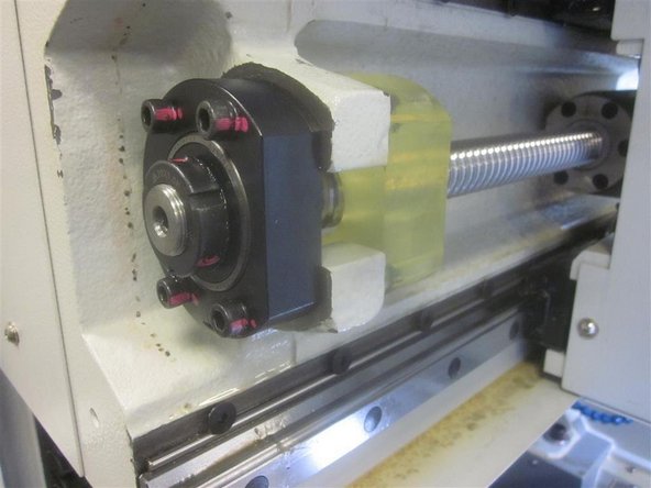
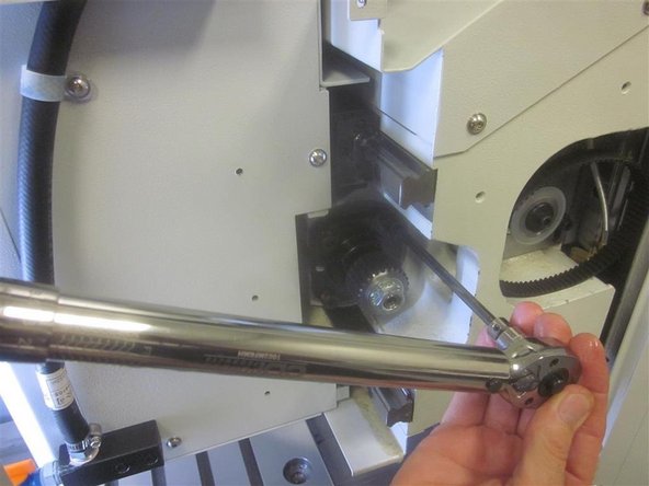
Remove the two front screws of the RH bearing housing. Remove the hex nut, star washer, flat washer, ferrule and woodruff key. Loosen the 10-32 lock screw on the clamp nut. Remove the clamp nut. Remove the cushion and bracket.
-
Remove the two rear screws of the RH bearing housing. Slide the housing off the ball screw, and set it aside. We recommend installing new bearings when changing a ball screw.
-
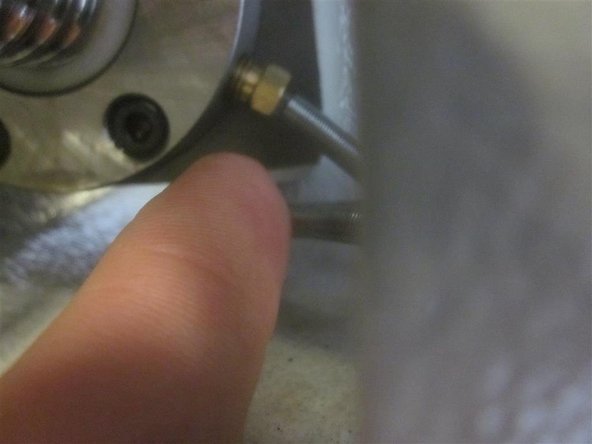
Remove the oil line from the ball nut on the LH side of the spindle.
-
-
-
Remove the cushion from the LH side casting. Remove the four (4) screws attaching the roller bearing housing to the LH side of the casting.
-
Remove the five (5) screws attaching the ball nut to the yoke/spindle casting.
-
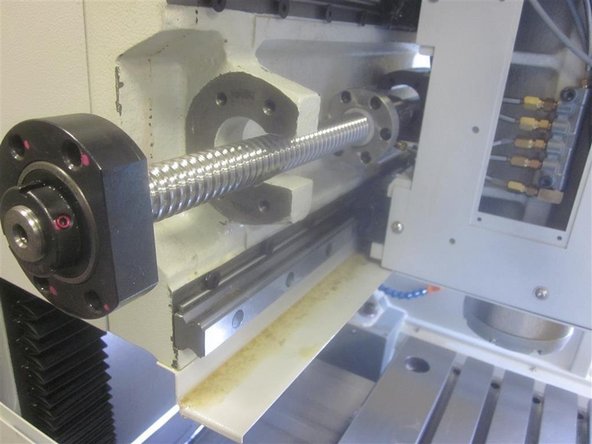
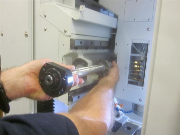
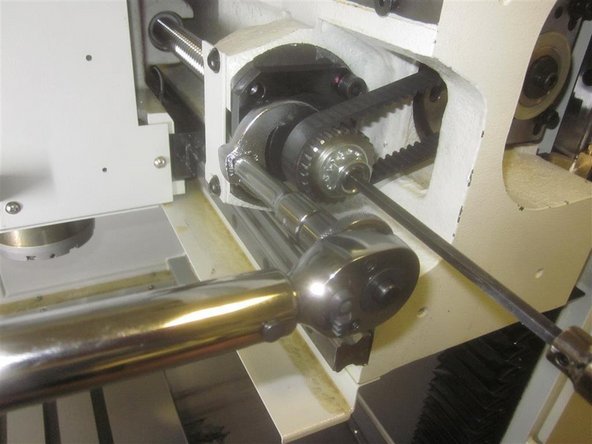
Remove the roller bearing and housing as a unit with the ball screw. Remove the ball screw by sliding it out from the LH side of the machine.
-
Set the ball screw on a bench and loosen the set screws on the lock ring nut. Using brass/aluminum stock, tap on the ends of the set screws to break loose the inserts underneath. Hold the ball screw from turning with a 6mm hex key and remove the lock ring nut. Remove the roller bearing/housing.
-
-
-
Thoroughly clean all parts and the machined contact areas prior to installation.
-
We recommend installing new bearings when installing a new ball screw. If you are "Not" replacing the bearings, use care when cleaning the associated parts as not to contaminate the bearings.
-
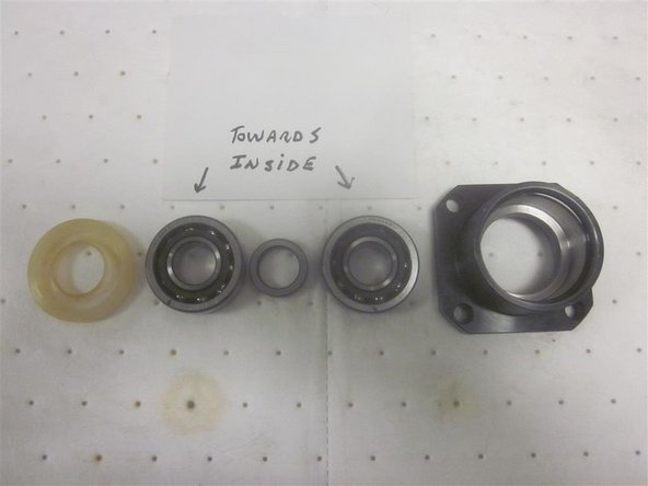
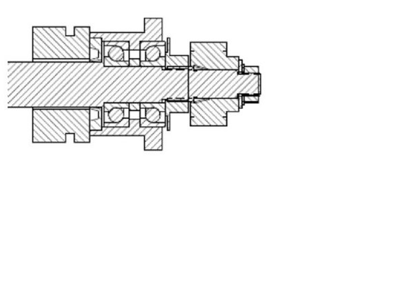
Install the angular contact bearings, spacer and seal. The bearings should be installed "back to back" as shown. Be sure the spacer is installed in between the bearings and the seal is installed correctly. The seals open side faces out.
-
-
-
Install the roller bearing in the housing and slide it on the end of the ball screw. It has a precision fit and may require a "tap" to seat it against the ball screw shoulder. Install and tighten the ring nut. Tighten the set screws.
-
Rotate the ball nut to approximately the location of the old ball screw. Lube all fasteners before beginning work.
-
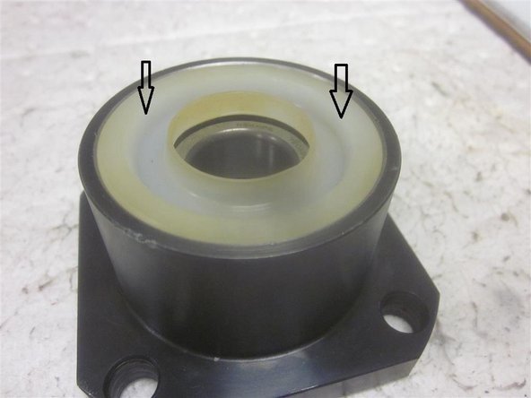
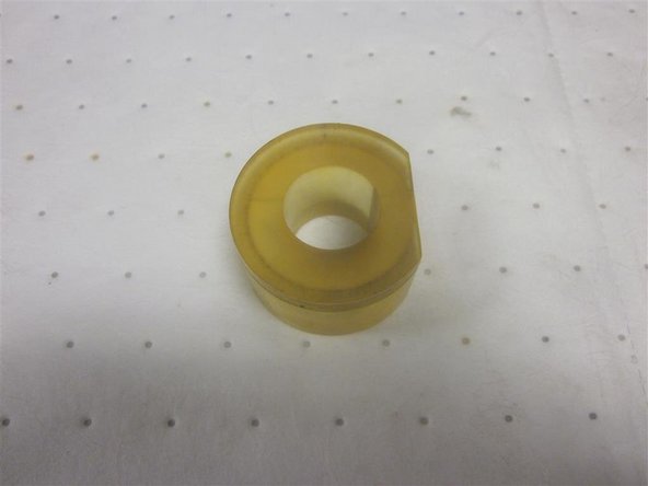
Note: On some early M10's, the RH cushion for the X-Axis is completely round, and must be installed on the ball screw first before fitting the ball screw through the RH bearing casting. Later models and all M11's are "C" shaped allowing it to be installed afterwards.
-
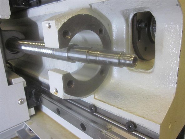
Slide the ball screw assembly through the yoke in the spindle casting from the LH side. Install the five (5) screws for the ball nut and lightly secure to the yoke. Install the oil line to the ball nut.
-
Install the bearing housing by carefully sliding it on the end of the ball screw. Install the two (2) rear screws of the bearing housing but not tight. Install the clamp nut and torque to 50 ft. lbs. Torque the lock screw to 60 in. lbs. Install the woodruff key, ferrule, sprocket, flat washer, star washer and nut. Tighten securely.
-
Note: The spacer in between the bearings may not be lined up. Use caution and wiggle the bearing housing a bit to guide it in place. Do not force the bearing housing onto the end of the ball screw.
-
Install the four (4) screws for the roller bearing housing and take up any thread. Do not tighten yet.
-
-
-
Rotate the ball screw moving the spindle all the way towards the right hand side but not against the cushion. This will align the ball nut with the angular contact bearings.
-
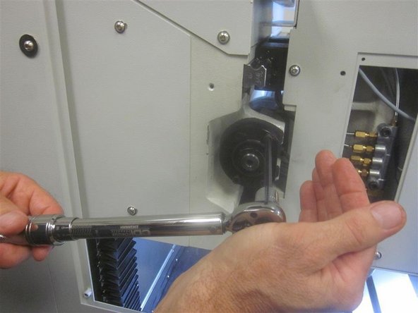
Install and tighten the front (2) screws of the RH bearing housing to the casting. Torque all to 11 ft. lbs. Tighten the five (5) screws for the ball nut to the yoke. Torque to 7 ft. lbs. (84 in. lbs.).
-
Install the cushion on the LH side of the casting. Rotate the ball screw moving the spindle all the way to the LH side, but not against the cushion. Tighten the four (4) screws on the LH bearing housing. Torque to11 ft. lbs.
-
-
-
Go to service code 505, and adjust the X motor to 180 (or the number you noted earlier. Rotate the ball screw until it touches the RH cushion, and let it relax. Back it off exactly one full turn, so the limit switch just lights. Install the belt and tension it, so it can only twist 45 deg. Torque the X motor plate screws to 10 ft. lbs.
-
Home the machine.
-
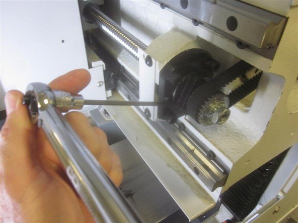
Check the rolling torque left, center and right. In DRO, jog the spindle to each position and press E-stop. Use the torque meter and slowly rotate the ball screw. It should be 10 in. lbs. or less and not vary more than 3 in. lbs. between. Average is 6 or 7 inch lbs.
-
If you get a high rolling torque number, check that the cushion (s) are not rubbing the ball screw. If the rolling torque is still high, it may be necessary to break loose the screws on the ball nut, bearing housing (or both) in the "high" positions and re-torque to allow better alignment.
-
Go back to service code 505 and check the index angle. It should be near your number or near180. It must be 180 + or - 45 (135-225). Mode out.
-
-
-
Note: With a new ball screw, it will be necessary to check tool locations and the front LH ball lock location.
-
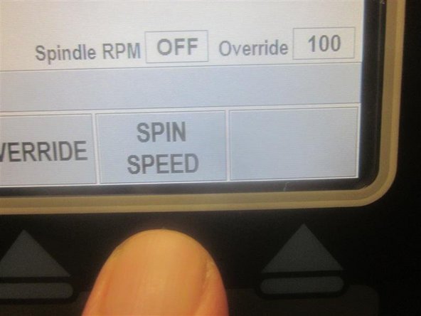
In DRO, set the spindle speed to 150 rpms and press ABS SET.
-
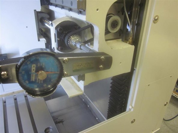
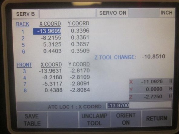
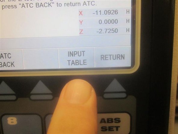
Go to service code 520, and bring the ATC forward (towards the operator). Press the "Input Table" key. Use the hand wheel to highlight a tool location. Using a co-axial indicator and tool holder, check a couple of tool locations noting if the X and Y numbers coordinate with the location with the new ball screw.
-
If you do change any coordinating tool location numbers in service code 520, make sure to press the "Save Table" key.
-
If things look good, send the ATC back and go to "Tool Loading." Check all tool locations for proper loading and unloading.
-
Look for excessive movement in the tool grippers as the machine cycles through tool loading/unloading, because they may be worn or damaged.
-
Excess up and down movement during tool loading might require adjusting the Z "tool change" height. If necessary, adjust it to ensure smooth operation. Use your service manual to perform this.
-
-
-
In DRO, set the spindle speed to 150 rpms.
-
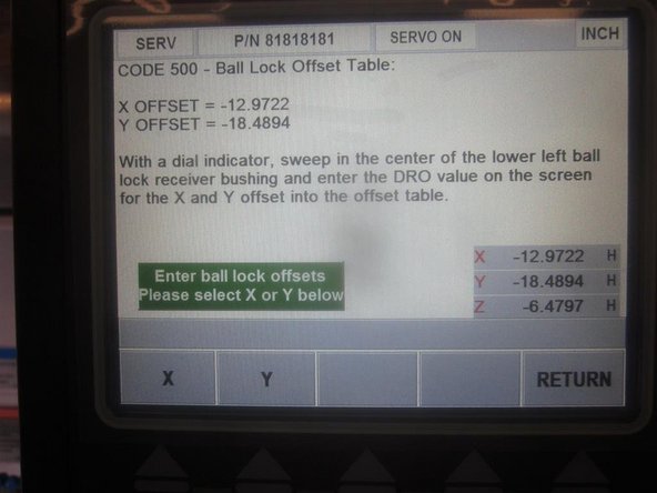
Go to service code 500 to check the front LH ball lock location.
-
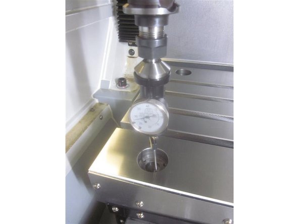
Use the DRO in the lower RH corner to determine the ball lock location.
-
Using the co-axial indicator, check the X and Y numbers against the numbers entered previously. If necessary, change the numbers. Select X or Y. Enter the number and press ABS SET.
-
-
-
On M11's, the Soft Limits are set when the machine is powered up and homed. For M10's follow the steps below.
-
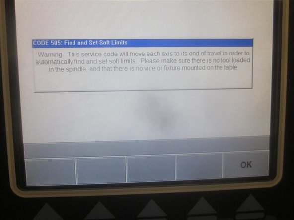
Caution: Remove all tooling from the table and the spindle before setting soft limits.
-
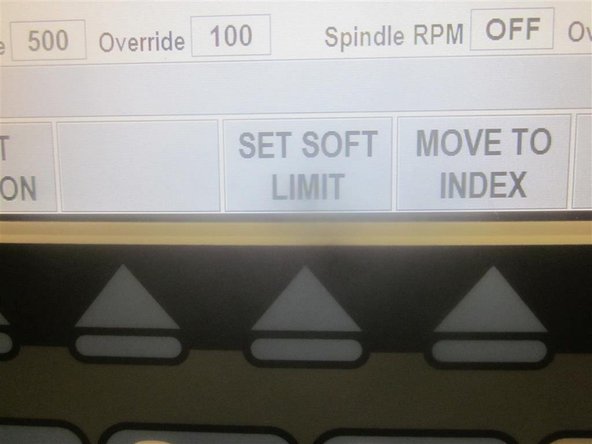
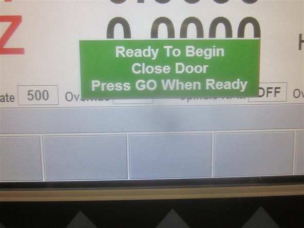
Go to service code 505. Press the "Set Soft Limits" key. A blue warning appears reminding the caution above. Press "Ok", then "Go." The machine will rapid all axis to set the limits. When finished it will be in 505.
-
Press the "mode" key.
-