Tools
Parts
No parts specified.
-
-
Remove any fixture or tooling from the work table. Remove any tool from the spindle.
-
Home the machine (if not already done so). In DRO jog the spindle to the center of the table.
-
Lower the Z axis near the bottom to allow access to all the sheet metal panels surrounding the spindle. Leave room to slide off the X axis bellows through the side openings of the cabinet.
-
Leave the power on until you start disconnecting electrical cables / components. It might be necessary to jog the spindle position for access.
-
-
-
Loosening all the screws first eases the panel removal and helps prevent stripping threads.
-
Jog the Z axis height to allow removing the X axis bellows covers.
-
Remove the LH and RH side access sheet metal covers.
-
Remove the RH sheet metal side cover accessing the electrical junction boxes.
-
Remove the LH side X axis ball screw bellows cover and the sheet metal cover for the spindle.
-
Remove the sheet metal covers on top and bottom of the spindle.
-
-
-
Press the Mode key, RSTR, Shut Down, Yes, then SHUT OFF the power to the machine at the main disconnect switch.
-
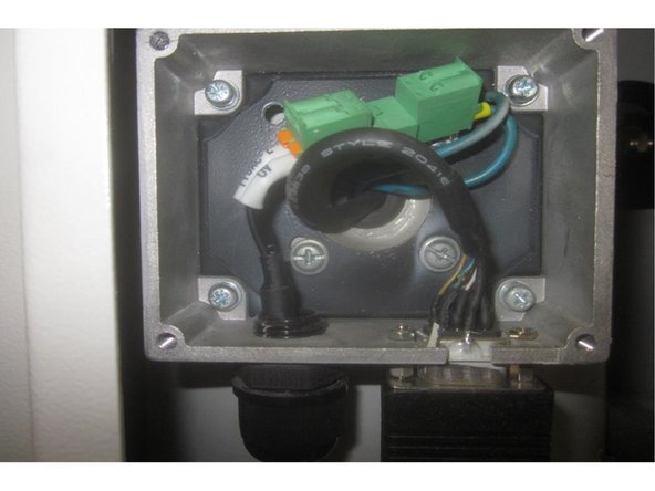
Remove the cover on the upper electrical junction box where the encoder and fan wires connect.
-
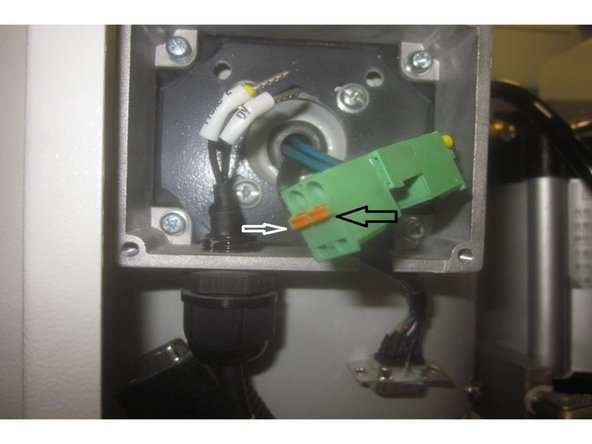
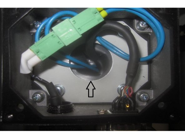
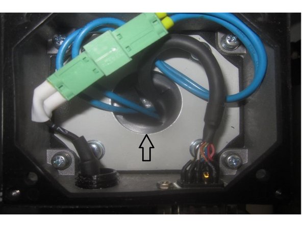
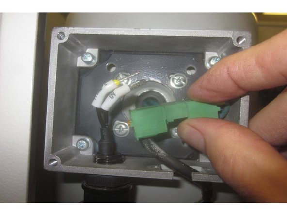
Using a small flat blade screwdriver, press the orange tabs on the tan colored wire connector to disconnect all the wires to the connector to allow removing the wires through the motor cover and junction box.
-
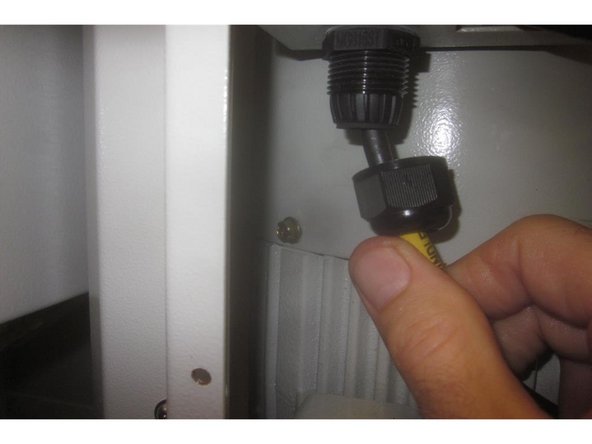
Loosen the nut on the strain relief for the spindle fan wires. Using a 22mm wrench remove the strain relief from the junction box separating the wires from the box.
-
-
-
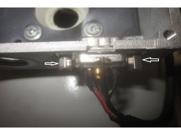
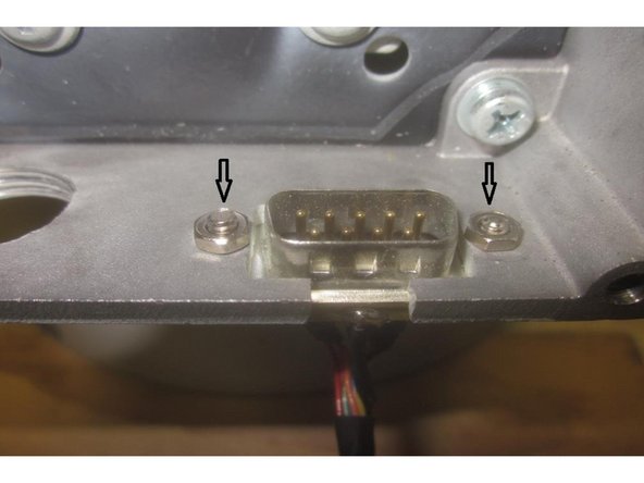
Using a 5mm 1/4 drive socket and 5mm open end wrench, remove the two (2) small nuts and jack screws retaining the encoder cable D-sub to the junction box. Use caution as these components are easily stripped or lost. Note: The junction box is threaded where the jack screws attach.
-
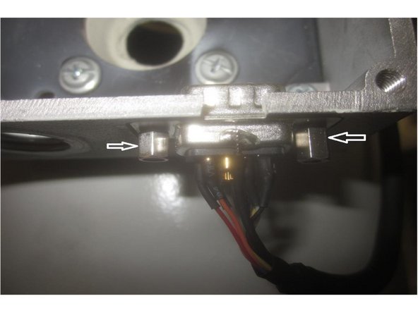
Observe the D-sub connector mounts from the outside on the bottom of the junction box. The box has a small relief for the connector to locate.
-
Note: The ground wire is attached to the outside of the connector on one side. When re-installing the connector the ground wire faces out.
-
-
-
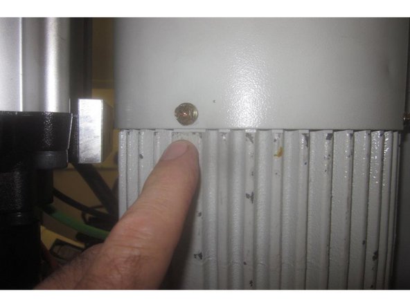
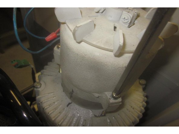
Using an 8mm wrench, remove the 4 (four) screws attaching the spindle motor fan cover to the motor.
-
Carefully lift off the cover guiding the fan and encoder wires through the junction box rubber grommet.
-
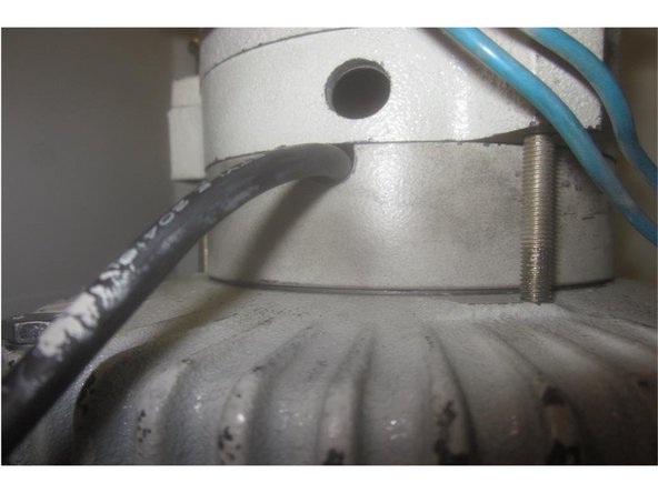
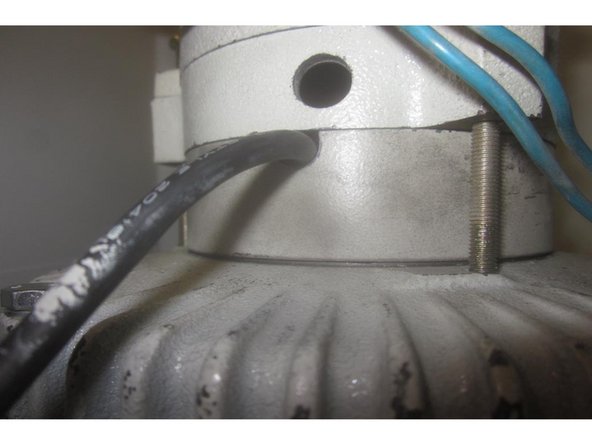
The fan housing and a spacer are attached with three screws. Note the opening in the spacer facing the RH side allowing the encoder cable through. Mark the spacer and fan for reference.
-
-
-
Loosen off the three screws that attach the fan to the motor. Lift off the fan. Remove the spacer (marked for reference) and guide it over the encoder cable.
-
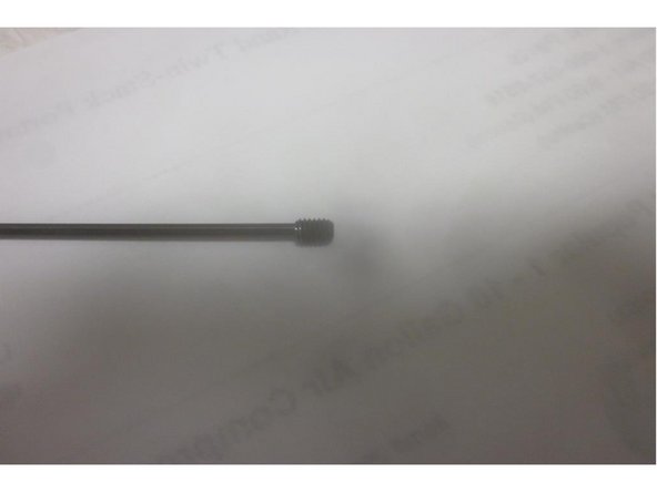
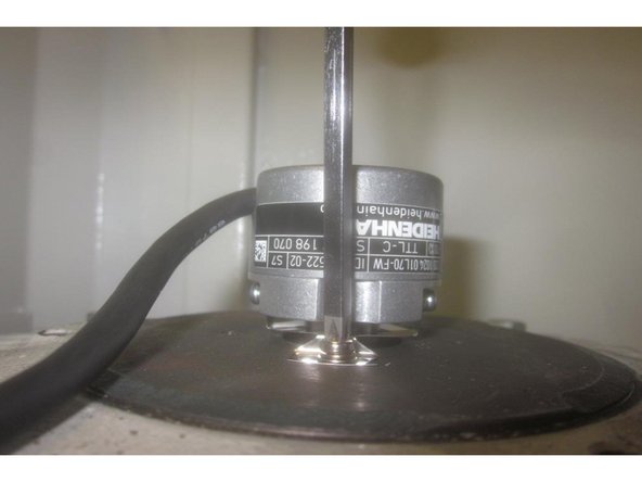
There are two (2) small set screws that tighten the encoder to the motor shaft. Using a 1.5mm hex key loosen both screws. Use caution as they are easily lost. Remove the two (2) small screws attaching the encoder to the motor housing and carefully remove the encoder.
-
-
-
Check the motor shaft for burrs or high spots. Carefully clean them off to ensure a slip on connection. Use crocus cloth, a stone or a fine file.
-
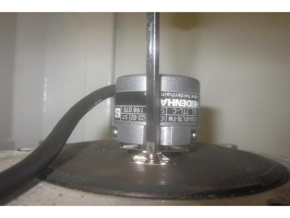
Carefully start the small set screws (1.5mm hex key) into the encoder and slide the encoder onto the shaft until the mounting feet touch the motor housing.
-
Install the two (2) small screws attaching the encoder to the motor housing and tighten securely. Note: The encoder cable faces towards the front of the machine. Tighten the set screws of the encoder shaft securely.
-
-
-
Install the fan spacer lining up the reference marks ( cable opening faces RH side of machine )guiding the cable into the slotted opening.
-
Install the fan lining up the reference marks and tighten the three screws securely.
-
Guide the encoder cable and fan wires through the fan cover / junction box and in stall the fan cover. Install the four (4) screws for the cover and tighten securely.
-
-
-
Install the D-sub connector and fan cable strain relief fitting to the junction box. The D-sub connects from the bottom where the box is relieved. Carefully tighten the jack screws and nuts. Note: The ground wire is attached to the side of the connector and faces out when re-installed.
-
Carefully install the orange encoder cable and tighten the nut on the fan cable strain relief fitting.
-
Connect up the fan wires to the tan colored connector. Depress the orange tabs and push in the wire. Blue wires on one side and black on the other. Note: The wires install in either position on the same side.
-
-
-
After re-connecting the wiring and cables install the junction box cover.
-
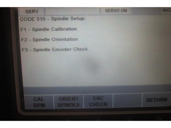
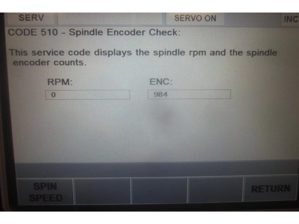
Before installing the sheet metal covers, power up the machine. Activate the servos and go to service code 510. Press the "Enc Check" soft key. Manually rotate the spindle and note the rpm and encoder position numbers change with movement. Mode out.
-
Before homing the machine, check that nothing will interfere with the axis' movement while homing.
-
Home the machine.
-
-
-
To perform "Spindle Orientation" you need a BT30 Tool holder with the retention knob removed.
-
Go to Service Code 520 and bring the ATC forward. Press the "Input table" key. Place the tool holder in position # 4. Using the DRO readout in the lower RH corner, move the spindle to the coordinating numbers for position #4. leave the ATC out and Mode out.
-
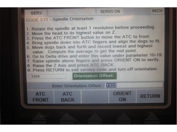
Go into Service Code 510 select the "Orientate Spindle" soft key. Follow the directions on the screen and section 6.22 in the service manual.
-
After completing Spindle Orientation go to Service Code 520 and send the ATC back. Go to "Tool Loading" and check several tool locations by loading and unloading tools.
-
In most cases no adjustments will be necessary to tool locations. Observe movement of the tool grippers and adjust if necessary to get smooth operation.
-
When assembling the sheet metal spindle covers '''Start All The Screws First". This eases installation and prevents stripped threads.
-


